

Tuttnauer Tiva 8-L Installation Guide
In this article, we’re going to give you the information you need to properly install your Tuttnauer Tiva 8-L. This guide comes as a part of our Free Tech Support Program. And if you have any questions, give us a call at 704-966-1650 Option 3 for our Free Tech Support line.
Installation
It is advisable that only furniture for professional use be positioned in the area around the machine, to avoid ruining them due to possible leakage of condensation water.
IMPORTANT NOTE! For a safe installation, the electrical disconnector / plug of the device must be positioned free from any obstacle and in a visible and accessible position for the operator, so that it’s easy to control it in case of emergency or prolonged safe disconnection.
HAZARD! Do not install and/or use the glasswasher in environments with flammable/explosive atmosphere.
WARNING! Make sure that the floor is fit to support the load of the equipment when in operation.
WARNING! Make sure that the machine is perfectly vertical and stable, using a spirit level, if necessary.
Unevenness of the machine surface and height can be adjusted with the two adjustable feet placed under the machine itself.
HAZARD! All electrical and water connections (loading/unloading) can only be carried out by specialized and authorized personnel and by consulting the relative diagrams.
Before machine positioning make sure that:
- All the components needed for installation and proper use of the machine were installed: main switch, water supply taps, drain and anything else needed.
- These components should have all the needed features and should be installed at the locations shown in the installation scheme.
WARNING! The use of unsuitable parts, and/or the implementation of installation procedures other than those shown on the installation diagram, will immediately void the machine warranty.
The characteristics of the electricity network must be compatible with the values required for correct operation indicated on the machine identification plate and on the technical data sheet.
The machine must be connected to an efficient earthing system (according to electrical safety standards).
IMPORTANT NOTE! The manufacturer is not to be held liable for any damage caused by improper grounding of the machine or faulty power supply.
Under the Counter Installation
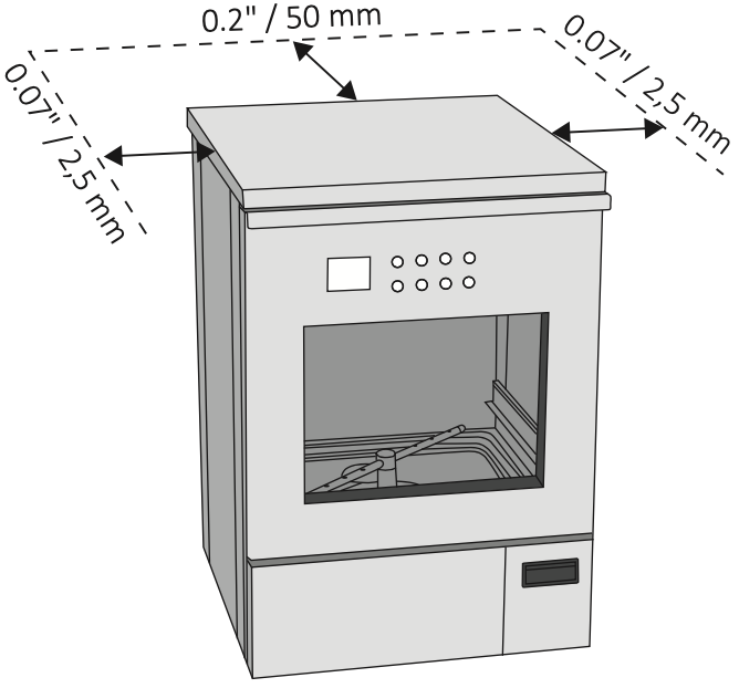
The under the counter machine can be inserted under a continuous worktop or under the sink’s drip surface. The recess niche must have a minimum space as shown in the picture above.
The presence of adequate air intakes must be guaranteed to allow the ventilation of the area behind the machine, in order to avoid creating a closed space without exchange of air with the room environment.
Electrical Connection
HAZARD! Only qualified and experienced personnel can connect the machine to the mains supply, in compliance with the current laws and regulations.
WARNING! In the single-phase version, the main switch of the power supply line must be a multi-pole circuit breaker, with adequate residual current protection.
WARNING! In the three-phase version, the main switch must be multi-pole circuit breaker, with adequate residual current protection, positioned near the machine and not covered by machines or other that may hinder its use.
The magnetic-snap safety system, or the fuses, must be calibrated according to the power indicated on the machine plate.
Make sure that the measured voltage is equal to the one reported on the identification plate of the machine.
Check that the voltage does not differ by more than 10% from its rated value.
Make sure that the electrical system is equipped with an efficient grounding connection.
Connect the cable that comes out of the machine to the wall socket. In case the machine has a three- phase connection (standard), connect the cable installed on the machine to the three-phase plug and insert it into the interlocked socket next to the machine (not provided).
The socket must be accessible after the machine installation. This facilitates verification of the electrical safety, e.g. in repair or maintenance interventions.
The machine must be supplied with current whose voltage, frequency and protection values correspond to those indicated on the data plate.
Additional indications regarding the electrical connection are shown in the installation plan.
IMPORTANT NOTE! The fuses must be in compliance with Standards IEC 60127-2, UL248-14, CSA C22.2.
Positions of the fuses (shown above)
1.) Fuses in the machine
HAZARD! Damaged fuses must be replaced by authorized personnel.
Electrical connection
Connection of the machine to the electrical mains must be made by qualified, skilled personnel.
WARNING! Power supply cable: it is compulsory for the retailer – installer to adapt the insulation class of the power supply cable to suit the working environment in compliance with current technical regulations.
Check that the electric specifications match those shown in the label.
The electrical connection must be carried out in compliance with current technical regulations.
Make sure that the primary voltage reading corresponds to the voltage indicated on the machine plate.
Check that the power supply voltage does not differ by more than 10% from its nominal value.
The frequency of the power supply voltage must not differ by more than 1% of its value.
Connection of the machine to the mains must be provided with an earth connection and an equipotential circuit as set forth by current standards.
Make sure that the electrical systems are efficiently earthed.
The earth conductor is to be connected to the earth terminal identified by the standard symbol (shown below)

The machine is equipped with a terminal identified by the relative symbol (shown below) for equipotential connections between appliances (see rules for electrical plants)

Connect the machine by using the power cable supplied with the machine.
In case of prolonged use of the machine it is recommended that you execute the disconnection procedure of the electrical connection by placing the dedicated safety device in “OFF” state.
The upstream electrical power line must be dimensioned and protected in accordance with current local regulations.
Electromagnetic compatibility (EMC)
The machine has been tested on electromagnetic compatibility pursuant to Standards IEC 61326-1 + EN 61326-1 and is suitable for operation in institutes such as laboratories, hospitals, medical practices and environments connected to the public electricity grid.
The high-frequency (HF) energy emissions of the machine are so small that interferences with electrotechnical equipment in the immediate vicinity are not likely.
The optimal positioning floor must be made of concrete, wood or ceramic tiles. In case of machine operation on floors made of synthetic materials, the relative humidity must be 30% to minimize the likelihood of electrostatic discharges.
Water Connection
CAUTION! The water in the wash chamber is not drinkable.
The quality of the water used must be compatible with the manufacturing materials of the machine, with the chemicals and with the process needs in the various stages of the procedure.
To have good washing results, the water must be soft and low in limestone. With hard water white patinas deposit on the objects to be treated and on the walls of the wash chamber.
For the correct operation of the machine, the water inside the washing chamber must have a maximum hardness of 0.7 mmol/l CaCO3 (3.9°DH / 7°fH). If the installation site does not have water with the required specification, the machine must be equipped with an internal softener (option available).
The water used in all the washing stages should be of drinking quality according to the “Guidelines for drinking-water quality, 4th edition” published by the WHO. A high iron content can cause rust on the load and in the special washing machine. If industrial water contains a higher amount of chlorides than 100 mg/l, the risk of corrosion significantly increases.
Water hardness conversion table:
| French degrees [°fH] | CaCO3 [mmol/l] | German degrees [°DH] | CaCO3 [PPM] |
|---|---|---|---|
| 0-10 | 0-1.01 | 0-5.60 | 0-100 |
| 11-15 | 111-1.51 | 6.16-8.40 | 110-150 |
| 16-20 | 1.61-2.02 | 8.96-12.20 | 160-200 |
| 21-25 | 2.12-2.52 | 12.76-14.00 | 210-250 |
| 26-30 | 2.62-3.03 | 14.56-16.80 | 260-300 |
| 31-35 | 0-5.60 | 17.36-19.60 | 310-350 |
| 36-40 | 6.16-8.40 | 20.16-22.40 | 360-400 |
| 41-45 | 8.96-12.20 | 22.96-25.20 | 410-450 |
| 46-50 | 12.76-14.00 | 25.76-28.00 | 460-500 |
| 51-55 | 14.56-16.80 | 28.56-30.80 | 510-550 |
| 56-60 | 5.66-6.06 | 31.36-33.60 | 560-600 |
The special washing machine is standard prepared for connection to cold and hot water. Connect the flow pipes to the shut-off valves for cold and hot water.
The machine must be connected to the water mains in accordance with current regulations.
If the water supply of the device has not been used for a long time, or if it is used for the first time, purge it by draining the water into a container or into a drain for a few minutes in order to remove any impurities, air bubbles and/or whatever may damage the machine and clog its filters.
| Cold water | Hot water | Deion. water | |
|---|---|---|---|
| Min. temperature | 41°F 5°C | 113°F 45°C | 41°F 5°C |
| Max. temperature | 86°F 30°C | 158°F 70°C | 86°F 30°C |
| Recommended flow pressure | 43 PSIG 300 kPa | 43 PSIG 300 kPa | 43 PSIG 300 kPa |
| Min. flow pressure | 29 PSIG 200 kPa | 29 PSIG 200 kPa | 29 PSIG 200 kPa |
| Max. flow pressure | 72 PSIG 500 kPa | 72 PSIG 500 kPa | 72 PSIG 500 kPa |
Connect the cold, hot and deionized (if available) water hoses, exiting the machine with their respective network connections, as shown on the installation diagram. It will be the responsibility of the installer to make sure that the temperature of the cold water supply is correct, otherwise proper washing of materials cannot be ensured. The connections for cold and hot water must not feed any equipment other than the glasswasher. During the washing cycle, this is necessary to prevent the subdivision of the water supply with other users, thus leading to a substantial increase in the time required to fill the chamber (in this case an alarm will be triggered to alert the user that the maximum time allowed for water loading is exceeded).
- If the machine is provided with a deionized water feeding system but the plant is not equipped with it, the cold and deionized water hoses should be connected together.
- The machine can be equipped with a built-in softener, which has the function of reducing the scale in the water supplied
- Connect the flexible hoses to the machine valves positioned in view at the back, making sure to connect them correctly based on the sales configuration.
- Make sure to connect the water flexible hoses in the positions shown in the picture below.
- Connect the water flexible hose to connections shown in the picture below.
- If present, install the Disconnector CA while maintaining a clear area of 6″ (150 mm) around the valve (For more information see the Installation Plan). The water supply taps must be capable of quickly stopping the water line, therefore, they must be equipped with a ball or a gate valve. They must also withstand the operating pressure of the water, as indicated in the technical data sheet.
Proper placement of the taps is shown on the installation plan.
HAZARD! Be careful in case of a blockage of the drain which could cause spill out of water and the risk of slippery floor.
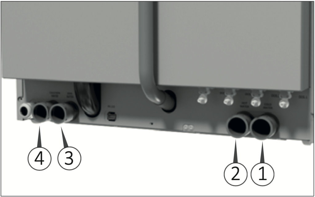
Water connections (shown above)
1) Cold water connection.
2) Hot water connection.
3) Deionized water connection.
4) Cold water condenser connection.
WARNING! The flow pipes must not be shortened or damaged
The water supply taps must be capable of quickly stopping the water line, therefore, they must be equipped with a ball or a gate valve. They must also withstand the operating pressure of the water, as indicated in the technical data sheet.
Proper placement of the taps is shown on the installation plan.
Aquastop System
The water connection hoses are fitted inside with two solenoid valves, connected to the float switch. If a water leak is detected, the float is triggered, causing the solenoid valves to close.
Models with Built-In Water Softener
The integrated function of the softener is used to reduce the amount of limescale contained in the incoming water. If the machine is connected with hard water, the result is a rapid degeneration with loss of function and performance.
Regeneration must be performed to keep the ionic resins active.
For machines equipped with a water softener, when
installed, it is necessary to enter the water hardness value by entering in programming menu.
Hardness in French degrees [°fH] Setting parameter Regeneration
0-10 Value 0 No regeneration
11-15 Value 30 every 30 cycles
16-20 Value 25 every 25 cycles
21-25 Value 21 every 21 cycles
26-30 Value 18 every 18 cycles
31-35 Value 15 every 15 cycles
36-40 Value 12 every 12 cycles
41-45 Value 9 every 9 cycles
46-50 Value 6 every 6 cycles
51-55 Value 3 every 3 cycles
56-60 Value 1 *Regeneration at every cycle
*Recommended only for expert users.
Actions for salt refill:
1) Open the door.
2) Unscrew the plastic cap of the salt box.
3) Pour 1.5 lbs (0.7 kg) of common salt into the box using the appropriate funnel.
WARNING! During this operation, check that the plastic cap is closed.
4) Insert the rack and start a normal washing cycle. The machine regenerates automatically.
WARNING! The washing cycle performed after the <salt loading> may not work.
Regeneration Salt
If the water softener was chosen when configuring the machine, the glasswasher is supplied with regeneration salt which will feed the device automatically during the regeneration process.
You must fill the salt tank every time the message “Refill salt” is displayed.
- Use only appropriate coarse-grain salt.
- Do not use kitchen salt, crushed salt tabs or other types different from those indicated, as it may contain insoluble substances.
- Do not pour cleaning liquids or other solutions in the salt tank.
WARNING! Failure to comply with these recommendations can lead to a malfunction of the water softening device. Just before the salt runs out completely, the display will show the message «Lack of salt». At this point, the salt should be topped-up as soon as possible, otherwise an error message will appear and it will no longer be possible to activate a new cycle if not by resetting.
The salt must be introduced through the chamber outlet inside the tank (#4 in “chamber filters section”). To introduce the salt, unscrew the cap (anti-clockwise) and fill the tank with salt funnel, paying attention not to pour salt outside the bowl then close the tank with the cap.
Salt Refill
Proceed as follows to refill the salt:
1) Delete the message on the display by pressing the RESET key for 5 seconds.
2) Open the door and remove any already inserted load.
3) Loosen the salt tank cap and insert the funnel.
4) In the first filling, introduce 0.13 US gal (0.5 l) of water to dissolve the residue salt. FIRST FILLING ONLY
5) Fill with salt up to the edge.The tank contains about 1.5 lbs (0.7 kg) of salt.
6) Thoroughly clean the edge of the salt tank.
7) Tighten the cap again.
8) Run a «Prewash» program to clean the salt residues inside the wash chamber.
- It is absolutely necessary to remove any salt residues that may have settled in the chamber after refill and before rinsing.
- After each top-up, start the «Prewash» program. In this way, any salt grains will dilute and rinse out. Salt residues and the overflowing water and salt solution can cause corrosion if they are not rinsed.
Following the instructions in the chapter “Starting the Machine”, start a «Prewash» program.
IMPORTANT NOTE! After the salt refill action, the first wash cycles may fail.
IMPORTANT NOTE! The “Refill Salt Tank” alarm may persist for few hours after the salt refill action, until the brine is being created. This will not affect the functionality of the device.
Automatic Regeneration
It is possible to have a water softening device that can completely regenerate at precise intervals. This process is fully automatic. Regeneration will be implemented before the selected program is activated.
This device must be preset by the service personnel during installation.
Regeneration can also be performed manually, regardless of the warning message on the display.
Connection of the Drain Tap
The machine is equipped with a built-in drain trap which must be mandatorily connected to the drain system of the building.
The user must carry out periodic maintenance of the drains and check that they are not clogged.
Before connection:
Supply the water connections with separate shut off valves;
Flush out the water pipes that are to be connected to the machine, to prevent clogging of filters and valves;
Procedure:
1) Connect the machine to water connections (Fig. 9).
2) Connect the grey drain pipe to the drain connection located at the back of the machine.
The correct positioning and sizing of the drain trap are shown on the installation drawing (see the Installation Plan).
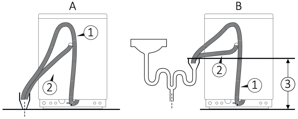
Water and drain system (shown above):
A) Floor drain connection.
B) Wall drain connection.
1) Hose connection waste water.
2) Hose connection capacitor discharge machine. 3) Minimum connection point 3.9″ (100 mm).
Maximum connection point 23.6″ (600 mm).
IMPORTANT NOTE! The glasswasher drain pipe must be maintained if backflow and other drainage issues are to be avoided. Keep the drain pipe free from kinks and knots, and minimize the number of twists and turns in the pipe. Be careful not to crush the pipe. If the pipe has been crushed, kinked, or otherwise damaged, consider replacing it to prevent future drainage issues.
Drain Connection
The drain connection must be properly installed according to the applicable instructions.
HAZARD! If the waste connection is installed incorrectly, the waste water could flow backwards into the machine’s chamber.
Water Hoses
The hoses:
- must be laid out so that they are not bent, pinched
Or tangled;
- may not be connected together before reaching the
Connection point;
- may not hang below the machine’s lower edge.
Connection Point for the Waste
- The connection point must have a capacity of 9.3 GPM (35 l/min) and must have a diameter of at least DN 1.5″ (40 mm).
- The hoses may be hung up using the accompanying hose holder.
IMPORTANT NOTE! The manufacturer is not liable in case of environmental pollution due to an incorrect use of the glasswasher.
Chamber Filters and Spray Arms
Chamber Filters
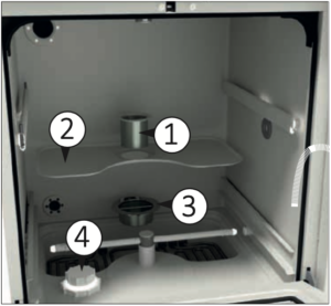
Filter Unit (shown above)
1) Central filter.
2) Mesh filter.
3) Chamber bottom filter.
4) Salt tank cap.
Insert the supplied filters in the specific positions. Constantly check the cleanliness of the filters, especially the chamber bottom filter (3).
Use this filter to have a high filtering, taking into account that it will have to be cleaned after each cycle performed to avoid an excessive build-up of dirt. Insert the mesh filter (2) and place it in the chamber seat. Finally, insert the central filter (1) in the mesh filter hole.
Spray Arms
The two spray arms are supplied loose to avoid possible breakage during transport. Place the two spray arms (lower and upper) in their seats and tighten them to the relative central pin inside the chamber (shown below).
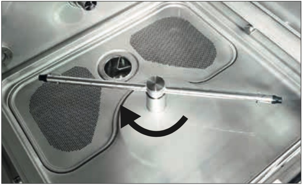
After fixing the spray arms, carry out a test by manually turning it, making sure that they rotate freely and without impediments.
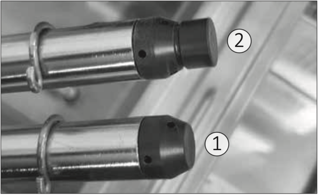
Spray arm rotation identification (shown above):
1) Spray arm without magnet for identification.
2) Spray arm equipped with magnet for identification.
After machine positioning, make sure nothing is preventing the chamber door from being freely opened. Make sure the machine is connected properly to the electrical supply, to the water supply and to the drain trap, then level it by adjusting its feet. After installation remove the PVC protection layer covering the panels, make sure the liquid tanks are full and the suction nozzles are properly inserted into the right tanks. A label next to the cap indicates the type of liquid to be used for each suction tube.
IMPORTANT NOTE! Spray arm assembly direction, the water outlet holes must face towards the inside of the chamber otherwise the spray arms will NOT work.
Chemicals
The glasswasher adopts as standard 2 pumps for dosing detergent and neutralizing agents, on request it can have up to a maximum of 4 dosing pumps for:
- Detergent agent.
- Neutralizing agent.
- Lubricant/Rinse aid.
- Additive.
Each dosing pump is monitored by a dosing volume control. This electronic control checks the dosing amount.
In the event of a lack of product, a message appears on the display and the program stops.
WARNING! It is recommended to handle the liquids with caution.
- Protect eyes, hands, clothes and metal surface from contact with liquids, which contain partially irritating agents and caustic substances.
- In case of contact with liquids, consult the instructions provided with the product.
- Use only suitable liquids for cleaning equipment. Carefully follow the manufacturer’s information.
- Keep chemicals out of the reach of children and outsiders. Possibly locked away.
- Use on only the manufacturer’s approved products.
- Do not use liquids for household dishwashers.
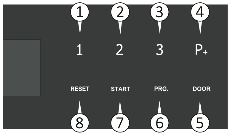
1) Set up a new tank with the chemical.
2) Remove the suction lance from the exhausted tank.
3) Insert the suction lance in the new tank.
4) With the door open, press and hold key P1 (1) to refill DOS1 for the detergent; key P2 (2) to refill DOS2 for the neutralizer; key P3 (3) to refill DOS3 for the lubricant/rinse aid liquid; key P+ (4) to refill DOS4 for additive liquid.*
Be careful not to reverse the position of the liquids.
*all numbers listed in parenthesis are attributed to the figure below
WARNING! Failure to follow these recommendations may damage the glasswasher.
With regard to maximum dosage for each program, follow the instructions of the chemical manufacturer.
To ensure efficiency of the dosing system, it is necessary to regularly carry out the maintenance operations set out in the chapter “Maintenance”.
The indications concerning the storage and disposal of chemical substances are provided by the respective manufacturers and must be observed.
Do not place the chemical containers on the glasswasher.
Completely empty the glasswasher before performing maintenance and before moving the machine to avoid contact with the chemicals and to protect the machine components.
Using and Storing Chemicals
Keep the containers tightly closed, stored in a dry place and protected from the sun, out of reach of children and outsiders. Possibly locked away. Optimal storage temperature: check the chemicals data sheet. The shelf life in the original containers is indicated on the chemicals’ labels. The manufacturer recommends a method for inventory management (first in- first out). The glasswasher can use up to 4 products for dosing liquids.
The manufacturer recommends using cleaning agents and chemical additives. The use of other products can damage the machine.
The flow meters of chemicals are calibrated according to the density of these tested products which ensure correct operation.
The following combinations of process fluids have been tested to verify the compatibility of the materials with the components inside the device, for devices placed on the market starting from the 1st of April 2021.
When chemical levels are low, a warning message appears on the display.
Chemical products dosing is set to an average value as recommended by the manufacturer.
When the actual dosing of the chemical exceeds the tolerance of 5%, the system goes into alarm.
Standard pre-installed chemicals:
- Detergent: T-Clean Tiva Detergent
- Neutralizer: T-Clean Tiva Neutralizer
IMPORTANT NOTE! If the machine does not use these recommended liquids, the flow meters must be recalibrated for the new liquids.
WARNING! Use only the chemical products indicated in the table. The use of non- certified products will void the warranty.
As always if you have any questions about this process or anything else please feel free to contact us and take advantage of our “FREE TECH SUPPORT.”
We also offer FREE VIRTUAL TECH SUPPORT to “See and Talk” with a “Real Time Live Technician” for any problems you may be in need of help with.
You can also use our “FREE MAINTENANCE PROGRAM”. Take the guesswork and worrying about what unit is due for maintenance and which maintenance cycle it is time for. We will keep track of all your autoclaves and let you know when it’s time for anything.