
Tuttnauer Tiva 8-MD Operation Guide
We have a previous article on installing your Tuttauer Tiva 8-MD, which can be found here. This article however, is all about operating your Tiva 8-MD the way Tuttnauer intended. And if you just want to talk to someone, call our Free Tech Support at 704-966-1650 Option 3.
Using the Machine
Before starting the machine, the operator in charge must have read and understood this whole manual, in particular the information given below.
“The operator in charge must be instructed on the risks deriving from accidents, on the devices prepared for the safety of the operator and on the accident-prevention rules provided by the legislation of the country of use of the machine. When realizing the machine, all potentially dangerous situations have been foreseen and appropriate protections have been adopted. However, the level of accidents caused by careless and awkward use of the machine remains high. Distraction, carelessness and too much confidence are often cause of injuries; as well as tiredness and sleepiness. It is, therefore, mandatory to carefully read this manual, in particular section “3 Safety and prevention”.”
Furthermore, before starting work, check that the machine is in order and that all parts subject to wear and deterioration are fully efficient.
Commission Instructions
These control operations (reported below) are performed to check if the machine works properly and should be performed when the machine installation is completed.
1) Open the tap that supplies water to the machine.
WARNING! The water should NOT flow into the chamber; otherwise the water loading solenoid valves are dirty or blocked due to long storage in the warehouse and therefore they must be cleaned.
WARNING! Check that there are no water leaks in the pipe fittings.
2) Check that the suction tubes (located in the lower part of the machine) within the corresponding tanks containing the liquids provided (detergent, neutralizer, and/or others), are correctly inserted.
3) Using the main circuit breaker, supply power to the machine.
4) Check that the water supply flexible hoses are properly connected.
5) At the beginning of the first cycle check the level probes of the liquid suction tubes (detergent, neutralizer and/or others): pull one tube at a time out of the container and check if the corresponding alarm flashes on the display, indicating the need for liquid refilling.
6) After running 3-4 washing tests, clean the water filters placed in the lower compartment of the machine (shown below).
7) Check that the drain trap does not show water leaks and is firmly secured to both the machine and the drain.
8) Check if the pumps correctly suck washing liquids. To do this, check that the liquid rises along the tube connected to them.
 Loading the Chemicals
When changing the tanks chemicals, it is required to perform the manual filling of the hydraulic circuit. This phase is important because it prevents any air bubbles present in the pipes from causing an interruption of the cycle following an incorrect reading of the flow meters.
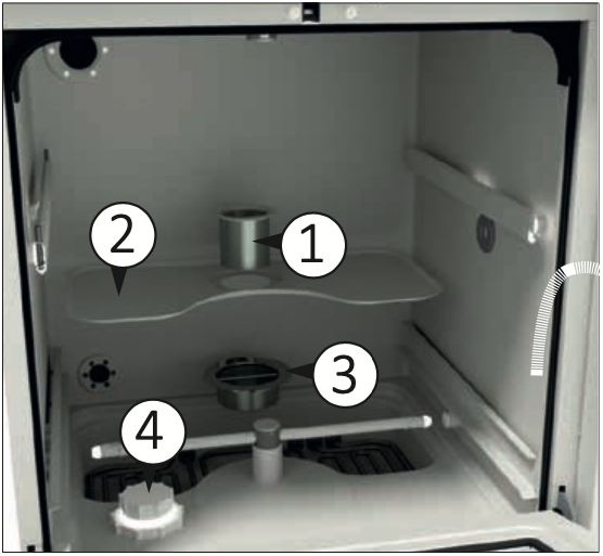
To fill the pipes after changing or refilling the chemicals, proceed as follows: (numbers match up to the graphic shown below)
1) Open the door using the “DOOR” button on the touch screen (4), if the door is already open, leave it opened;
2) Remove the rack if inserted, in order to have full visibility of the washing chamber;
3) Press and hold the button corresponding to the dosing pump you wish to activate to manually load the hydraulic system: key P1 (1) on the touch screen for pump DOS1; key P2 (2) on the touch screen for pump DOS2; key P3 (3) on the touch screen for pump DOS3; key P+ (4) on the touch screen for pump DOS4.
4) Wait a few seconds to see in the lower right part, the area where the chemical inlet holes are present, a constant flow free from air bubbles.
5) Release the button and repeat the sequence from 3 to 4 for the other dosing pumps that need to recharge the hydraulic circuit.

CAUTION! This phase must be performed at the first installation of the machine, in this case, let the liquid flow for a few more seconds to ensure the correct and full loading of the hydraulic system.
Before Use
The washer disinfector can be used for cleaning and disinfecting:
- medical and dental instruments;
- keys, trays, containers;
- hollow instruments, e.g. suction cannulas, fixing them to the appropriate supports, using the suitable adapters.
Emergency Door Release
In the event of a blackout, or any other need in which it becomes difficult to open the glass-washer door, there is a manual emergency release that can only be activated if the door cannot be opened normally.
HAZARD! If the emergency release is used while a program is running, very hot water and chemicals may leak. Therefore, there is a danger of burns, scalding and irritation.
HAZARD! In the case of an emergency release of the door, the load might be contaminated. Be careful while handling it.
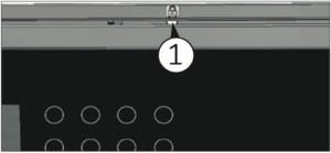
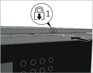
Release the door:
1) Push the key supplied in the pack horizontally into the gap between the door and the lid or worktop (1 Fig. 14.1), to position the key correctly, follow the position indicated on the label (1 shown below) on the door handle.
2) Upon the door unlock take out the key.
In case of program interruption, proceed with a new treatment of the load.
Preparing the Load
WARNING! The maximum weight that the open door can withstand is 66 lbs (30 kg). The maximum volume of the wash chamber is 44 US gal (165 l).
The instruments to be washed must be placed on the relative racks, making sure that they do not overlap one another.
IMPORTANT NOTE! The cleaning quality depends on the correct loading of the instruments.
Empty any residual liquids from the instruments and containers before inserting them in the chamber, washing all residues well (e.g. disinfectant solutions) in cold water.
Remove non-water soluble residues such as composites, cement and amalgam in compliance with current directives.
Insert the individual instruments in the appropriate supports or baskets and never directly into the base basket.
If necessary rinse the wash load briefly with water to avoid introducing coarse soiling into the machine.
Remove all stoppers, corks, labels, sealing wax residue, etc.
Make sure that the instruments do not come out of the containers.
Make sure that the instruments do not fall off the racks and inserts and do not hang from the grid bars.
Insert the hollow instruments into the appropriate injectors.
Insert the other instruments into the adapters with silicone insert.
Check that injector and connectors are securely held in position in the baskets or inserts.
Position container-shaped objects so that liquids can flow easily and, if possible, place tall and heavy tools in the centre of the rack.
Place pointed or sharp objects in such a way as to prevent anyone from being injured by them.
WARNING! Sharp or pointed objects can result in serious injury when loading or unloading
Components with special geometries must be arranged so as to allow the water to flow out.
Introduce only suitable steel instruments, resistant to corrosion.
Objects made completely or partially of plastic must be resistant to high temperatures.
Nickel-plated and chrome-plated and/or aluminum instruments and tools may not always be suitable for machine treatment. They require special process conditions.
If possible, disassemble the modular instruments following the manufacturer’s instructions and treat the individual parts separately.
Transmission instruments with fibre optic rod are considered resistant, while fibre optic beams may be subject to premature wear.
Treat small instruments and parts in special inserts or closable baskets.
Before the automatic treatment, check that the lumen and hollow body instruments can be treated internally and remove any obstructions.
Carefully place the load in the supports.
Objects must not be put inside each other nor cover each other. Do not place objects so close to each other that they cannot be washed properly.
Arrange the load so that all surfaces can be reached by the washing liquid. Otherwise they will not be cleaned!
Place the objects so that the liquids can flow out
without hindrance.
Tall, narrow, hollow and heavy items should be placed in the centre of the rack. This will ensure better water coverage.
When arranging the load, make sure that the spray arms are not blocked by the load itself.
After treatment, the transmission instruments must be cleaned according to the manufacturer’s instructions. After treatment, before reusing the transmission instruments, check that they are working properly, e.g. by spraying liquids into the sink.
Summary of the Rack Loading Operations
Depending on the load, special nozzles or adapters may be required for proper internal cleaning.
Sequence for loading the rack/trolley:
- Fill the rack/trolley by arranging the instruments so that all surfaces are reached during washing.
- Insert the rack/trolley into the chamber.
- Close the door and start the washing program.
Handpieces
Handpieces must be washed and rinsed both internally and externally. For this purpose, they require the use of racks/trolleys with special injections.
Trays
Trays must be positioned in the specific slots of the tray holder insert.
Treatment of Dental Instruments
WARNING! Insert only instruments suitable for automatic treatment in washer disinfector, according to the manufacturer’s instructions. In particular, follow the information provided by the same manufacturer. Despite compliance with the manufacturer’s instructions, in case of damage or alteration of the instruments, the responsibility will be borne by the instruments manufacturer.
Before starting the treatment, check that:
The external surface of the instruments is clean of material residues (E.g. dental cement, etc.).
The air and spray channels must be clean.
Finally, carry out a test. Use the recommended liquids (see chapter “Using and Storing Chemicals”).
Care of the instruments
Major manufacturers recommend drying the spray/ air/water channels immediately after cleaning and disinfection using clean compressed air with suitable maintenance products. It is recommended to follow the specific instructions.
Treatment of Ophthalmic Instruments
WARNING! Only insert instruments designed for automatic treatment in washer disinfector. Carefully follow the instructions provided by the instrument manufacturer.
HAZARD! Do not insert instruments intended for interventions on the optic nerve and which come into contact with the retinal tissue.
WARNING! In case of damage or alteration of the instruments despite compliance with the manufacturer’s instructions, the responsibility will still be borne by the instrument manufacturer.
WARNING! The treatment of ophthalmic instruments requires the use of deionized water.
Comply with the following for automatic treatment:
Use a slightly alkaline detergent for cleaning. Use a citric acid-based neutralizer for neutralization. Never use chemicals during the last rinse.
Rinse the hollow instruments after the application and check that the deionized water passage is free before the automatic treatment.
Insert the hollow instruments into the rinse bar, specially designed for this use.
Make sure that no deposits form on the instruments.
Dry the hollow instruments with compressed air after the treatment in order to remove all residual humidity.
Follow the manufacturer’s instructions with regard to the maintenance of instruments/accessories for loading.
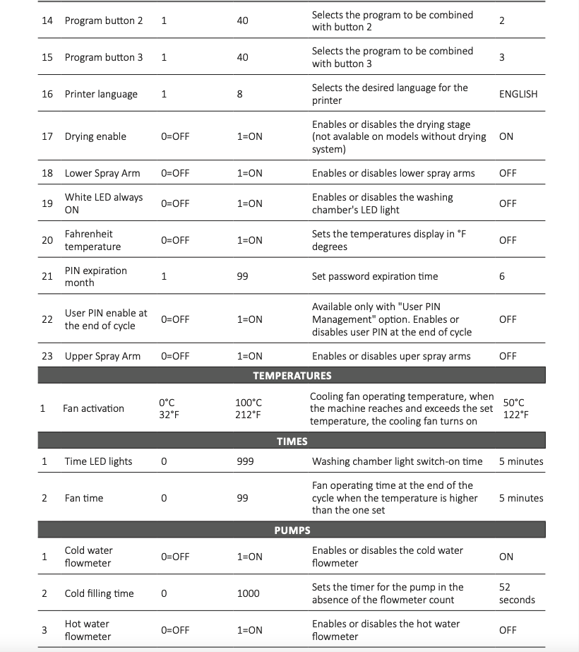
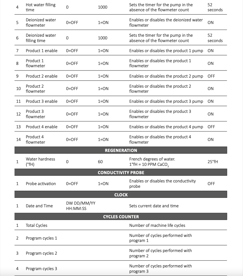
Programs
The machine leaves the factory with presetting washing programs already entered in the settings menu.
Suggested Programs vs. Configurations
For a good result, it’s important to choose the right program together with the right load/configuration. To select the programs available, use key P1, P2 or P3 (see Fig. 15) depending on the most suitable program for the level of dirt of the load.
To select the programs available, use key P1, P2 or P3 (see panel graphic in “Loading the Chemicals” section of this article) depending on the most suitable program for the level of dirt of the load.
Program Structure
- Drain: It is used to empty the washing chamber.
- Pre-wash: Pre-wash is necessary to eliminate coarse dirt and foamy substances.
- Wash: Depending on the load, washing normally takes place at 113°F- 149°F (45°C- 65°C), adding the appropriate detergent.
- Rinse: The rinsing operation eliminates and neutralizes the chemicals of previous washes.
- Disinfection: Process to inactivate viable microorganisms to a level previously specified as being appropriate for a defined purpose, deionized water (if available) should be used during the disinfection phase.
- Drying: Sufficient drying reduces the risk of corrosion caused by the residual humidity on the load (not available for models without drying system).
Starting the Machine
After checking the integrity and full efficiency of the machine, proceed with start-up:
- Power the machine using the main circuit breaker.
- Open the door (key 5, see panel graphic in “Loading the Chemicals”) to introduce the rack.
Before Starting the Program
Before starting each program, check:
- That the filters, positioned on the bottom of the chamber (Fig. 11) are perfectly clean. Clean them, if necessary.
- The nozzles of the upper and lower spray arms must be free and clean.
- Products must be arranged correctly.
- The spray arms must be able to rotate freely. The machine constantly monitors the rotation speed during the program (optional).
- Liquid containers must be sufficiently filled. Check for any messages on the display before starting the program.
Closing the Door
Load the instruments and introduce the rack.
Close the door and push it until the lock is activated. The door can be unlocked and opened at any time before the program starts, by pressing the Door (key 5, see panel graphic in “Loading the Chemicals”).
Selecting the Program
WARNING! Always follow the indicated procedures. Inattentive and frivolous use of electrical devices may lead to risks for the operator.
The manufacturer is not liable for possible damage caused by uncontrolled use of the device.
After selecting the program with relative key, the display shows the selected program and the operating time and temperature.
To start a program, press the START key (7 Fig. 15). Time counter use the first cycle to self calculate the time for each cycle.
Program Execution
Once the program has started, its progress can be followed on the display. The display shows the program phases during operations.
WARNING! The program can be interrupted at any time. However, it must be remembered that once interrupted, it must restart from the beginning. Only if it is interrupted in the drying phase can the cycle be considered completed successfully. The instruments must be dried.
WARNING! In case of contact with the fluids inside the chamber after the cycle has been interrupted before the end of the disinfection phase and consequent opening of the door, immediately contact the nearest health center.
Pre-Wash
Pre-wash is carried out with cold water (optional softened water) and without liquids. It mechanically dissolves encrusted organic materials and all proteins on the surface of the instruments. Avoid too high water temperatures.
Wash
It is the actual cleaning cycle. The cleaning chamber heats up until it reaches the specific temperature for the selected program, a temperature that remains stable for the holding time. The cleaning liquid is automatically introduced before the start of the holding time.
Rinse
Rinsing is carried out with cold water, the machine is standard equipped with the second pump with which it is possible to carry out the neutralization cycle by introducing neutralizing liquid which is designed to reduce the alkalinity and clean the instruments from residues soluble in acid, e.g. limestone and rust.
Disinfection
Thermo-disinfection is carried out with deionized water, depending on the setup of the machine, it is possible to introduce the rinse aid to improve the drying phase.
Drying
The instruments are dried internally and externally with filtered hot air. Good drying reduces the risk of corrosion caused by the residual humidity on the load. Instruments with a very small internal diameter must be dried further.
WARNING! If the drying phase is disabled, the machine will interrupt the cycle at the end of the rinse phase. It is the responsibility of the user to dry the instruments that have just been washed, using suitable cloths and following the instructions contained in the instruction manual for each individual instruments washed.
WARNING! If the drying phase is disabled, the instruments must NOT be left inside the machine, at the end of the cycle, wet, for longer than 5 minutes. This is to prevent the proliferation of bacteria and microorganisms. The manufacturer declines any liability for contamination of the instruments during the manual drying stage.
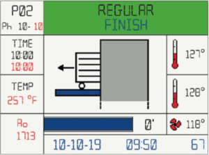
Program End
The message «Finish» with a green background on the display indicates that the program has been carried out correctly. Unlock the door by pressing the Door key (5 Fig. 15) and open it.
IMPORTANT NOTE! Open the door immediately after the end of the program to avoid condensation forming.
Check the results at the end of the cleaning process. The instruments must be completely clean and dry.
IMPORTANT NOTE! Hollow instruments with a small internal diameter must be dried further with air.
Check hollow instruments and retreat them if necessary. The hole (lumen) of hollow instruments must be free.
The injectors must be correctly placed on the connection tube in the cleaning chamber.
The nozzles and connections to the base grid must be firmly fixed.
If these checks are positive and the program has been carried out without interruptions or malfunctions, the load has been successfully cleaned and disinfected.
Extracting the Load
At the end of the program and when extracting the load:
Do not force the door open to avoid damaging the device or creating a hazardous condition.
WARNING! Particularly large instruments can be very hot at the end of the program. Allow instruments to cool down before removing them. Use adequate gloves that protects against burns.
WARNING! Failure to follow recommendations can cause burns.
Control Panel

The control panel consists of 8 keys and a 3.5 inch LCD display. All keys, except key “3”, are multi-function, depending on the action being performed in a specified state of the device.
Here below the description of the control panel standard (STD) and special (SPC) functions. Later on, with the description of how the machine works, we will find these symbols again.
IMPORTANT NOTE! “User Pin Management” option on request. The special functions (SPC) related to the username and password settings for the USER are not available if the option is not enable.
1) P1
STD: select program 1;
SPC: “1” character for the custom password; SPC: navigate upward in the menu;
SPC: change the value of the highlighted parameter.
2) P2
STD: select program 2;
SPC: “2” character for the custom password; SPC: navigate forward in the menu;
SPC: change the value of the highlighted parameter.
3) P3
STD: select program 3;
SPC: “3” character for the custom password;
4) P+
STD: select the next program (proceeding by +1 at a time upon program 40);
SPC: delete incorrectly typed field.
5) Door
STD: open the door at the end of the program;
SPC: exit from parameters and programs.
6) Prg
STD: enter to the program menu;
SPC: “C” character for the custom password.
7) Start
STD: enter the selected menu item;
SPC: continue to the next parameter;
SPC: “B” character for the custom password.
8) Reset
STD: stop a running program;
SPC: return to the previous menu item;
SPC: “A” character for the custom password.
Colors of the Keys
Depending on the menu function you are using, the keys get highlighted with different colors:
- White light: indicates the keys that can be used in that particular action.
- Red light: indicates the function “go back to the previous menu” if associated with the Door key; indicates the function “delete the characters typed” if associated with the P+ key.
- Green light: indicates confirmation of the action.
On any screen and for any action you can only use the highlighted keys.
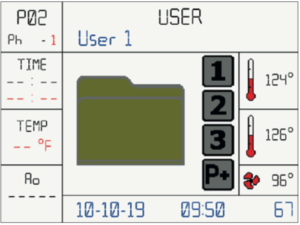
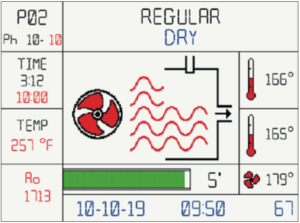
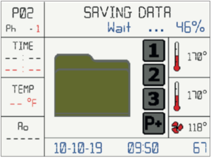
Display
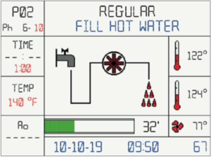
The LCD display shows the status of the machine. The images show the various phases and the current operation. For example: if the machine is loading water, the display will show the image of the tap, of the water flow meter and of the water being loaded. If water is cold, droplets will be blue and if water is hot, they will be red. The temperatures are set in degrees Celsius or Fahrenheit. The images are animated, to show how the current operation evolves.
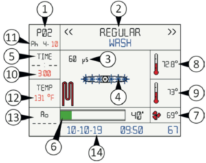
Description of the display (shown above):
1) The number of the running program is displayed (e.g. P02 = program 2);
2) It displays the phase the machine is running. If the machine is going to run a wash cycle it will display the writing «Wash». When the machine displays an alarm that space background turns red and the message shows the number of the alarm and a brief description;
3) Water conductivity value in microsiemens (if conductivity probe function is enabled);
4) Several animated images showing the current status of the machine are displayed;
5) The elapsed phase time from the moment the temperature set for the phase (see 12) has been reached is displayed;
6) Bar indicating the progress of the program; if the program is ending, the bar will be almost entirely green;
7) The temperature measured by the PT1000 probe, placed after the air heater, is displayed to indicate the temperature of the air entering the chamber;
8) It displays the temperature measured by the first PT1000 probe placed in the chamber;
9) It is the display of the temperature measured by the second PT1000 probe placed in the chamber. The temperature detectable by the two probes must not differ from each other by more than 36°F (2°C);
10)Time for which the device should maintain the set temperature (see 12);
11) Phase of the program;
12) Temperature set for the current phase;
13) The A0 value is displayed during disinfection; 14)Date and time are displayed with the machine in stand-by.
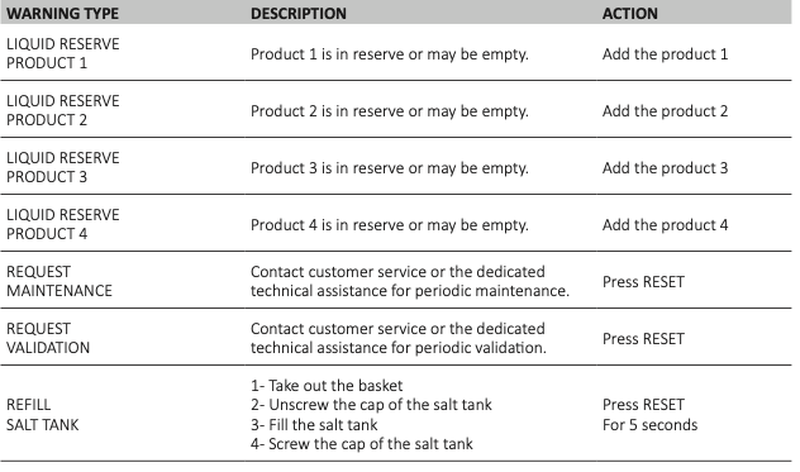
Messages on the Display
On the display of rack insertion, messages may be displayed, such as:
- Product 1 liquid reserve: meaning that the liquid inside the product 1 tank is finishing and must be replaced;
- Product 2 liquid reserve: meaning that the liquid inside the product 2 tank is finishing and must be replaced.
When the cycle has finished the following message appears: «Finish» and a green light appears in the chamber. At this point the door is unlocked and you can unload the rack with the washed items.
Bluetooth Enabled
If bluetooth is enabled, the following icon will appear on some display screens:
 If bluetooth has been disabled the following icon will be displayed:

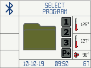
Display Screens
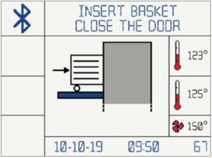
After starting the machine, following the instructions in chapter “Starting the Machine”, the display will show the images indicating step-by-step the operations in progress.
1) Once the machine has started, the display shows the screen indicating door open and the invitation to insert the rack with the instruments to be washed. Then insert the rack with the instruments and close the door.
WARNING! The door must be tightly closed until you hear the classic closing «click», otherwise the program will not start.
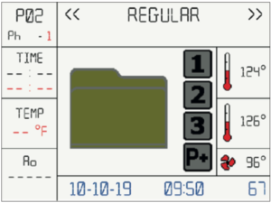
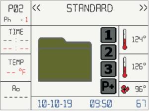
2) With the machine started and door closed, the screen for selecting the programs will appear. Press the selected key (P1 or P2 or P3 Fig. 13) on the control panel. To access subsequent programs (if stored), press the key «P+» several times.
3) Optional: once the program is selected, the screen for selecting the user will appear. Press the key P1 or P2 on the control panel to navigate upward and forward in the user list. Then press Start.
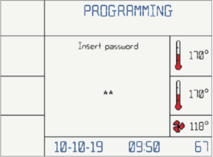
4) Optional: enter the user password: use the key P1, P2, P3, Reset, Start and Prg on the control panel to digit the correct password (See Fig. 13 for key description).
Program 2 Regular
Phase 1
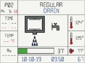
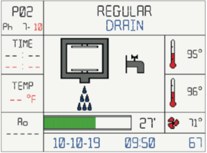
5) The machine starts the automatic work cycle and discharges any residual water present in the chamber.
Phase 2
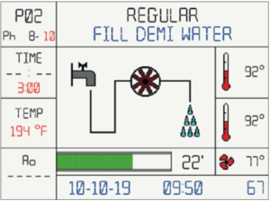
6) Self-loading of cold water. During the self-loading phase the chamber will be filled.
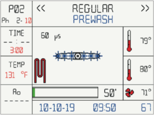
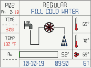 7) Prewash phase begins
 Phase 3
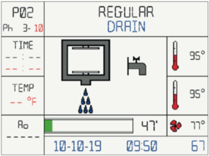
8) At the end of the prewash phase, the water is automatically discharged.
 Phase 4
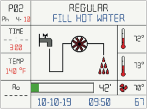
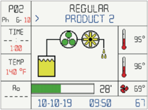
9) Self-loading of hot water. During the self-loading phase the chamber will be filled.
 10) Wash phase begins: the machine will rise the water temperature to the presetted value and will keep it for the presetted time.
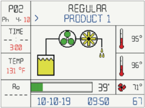
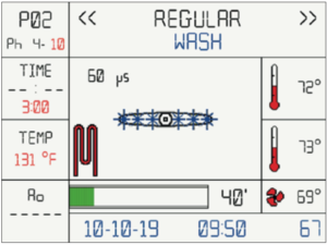 11)When the water reaches the 35°C (95°F), the peristaltic pump 1 will dose the detergent.
 Phase 5
12)At the end of the wash phase, the water is automatically discharged.
 Phase 6
13) Self-loading of hot water. During the self-loading phase the chamber will be filled.
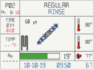
 14)Rinse phase begins: the machine will rise the water temperature to the presetted value and will keep it for the presetted time.
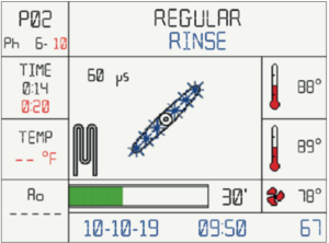 15)When the water reaches the 35°C (95°F), the peristaltic pump 2 will dose the neutralizing agent.
 Phase 7
16)At the end of the rinse phase, the water is automatically discharged
 Phase 8
17) Self-loading of deionized water. During the self- loading phase the chamber will be filled.
 18) Rinse phase begins: the machine will rinse the instruments while checking the conductivity of the water. At the end of the phase, if the conductivity will be below a preset value, the machine will proceed to the next phase. If the check is negative, the machine will repeat phases 7 and 8 again. If the second check will fail, the machine will show an error and stop the cycle.
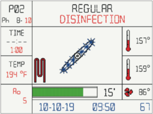
 19) Disinfection phase begins: the machine will rise the water temperature to 194°F (90°C) and will keep it for 5 minutes.
 Phase 9
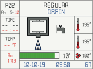
20) At the end of the disinfection phase, the water is automatically discharged.
 Phase 10
21) Dry phase begins: hot air is blown inside the chamber at a preset temperature and kept for the preset time.
 22) End of the «REGULAR» cycle. Open the door and remove the rack.
 If, for any reason, it is necessary to interrupt the cycle, simply hold down the RESET key for a few seconds until an audible alarm (buzzer) is heard and an alarm screen appears on the display.
Once the problem is resolved, resume the cycle from the beginning. If the problem cannot be solved, contact the technical assistance.
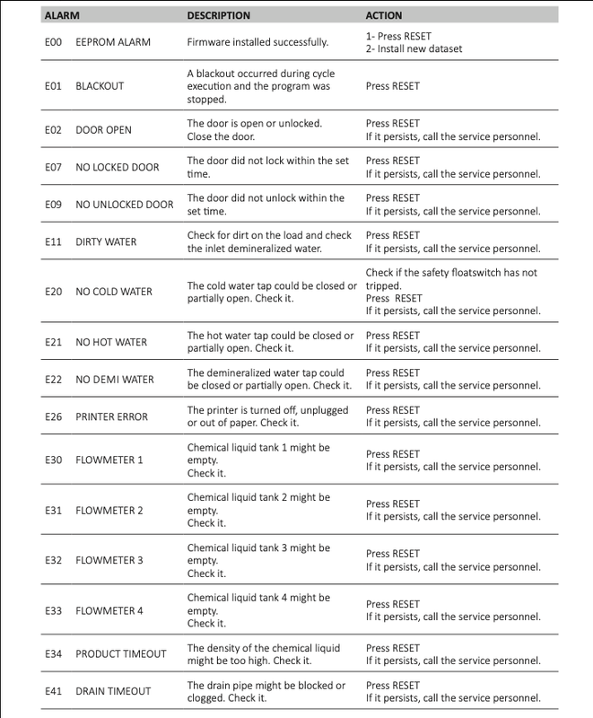
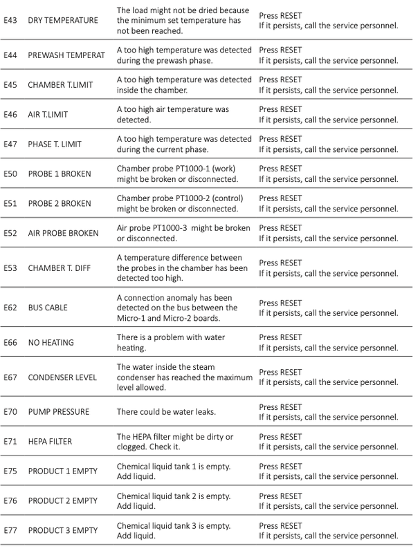
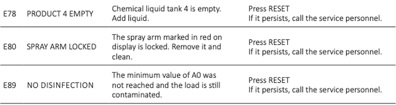
Alarm messages
The machine is equipped with an alarm system that indicates malfunctions detectable with an audible signal (buzzer), a screen on the graphic display of the control panel and a red led light in the chamber.
At first the image concerning the alarm is displayed (for 5 seconds); then the alarm description is displayed (for 10 seconds).
The image and text alternate until the alarm is reset.
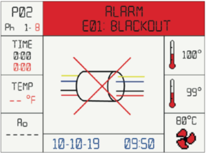 If the program is interrupted because of an alarm, the display will show the message «No disinfection stop- alarm». Follow the message shown on the display to reset the alarm.
IMPORTANT NOTE! If the RESET button is pressed during the wash cycle, the program is interrupted and an alarm is displayed with the message «No disinfection stop – user». Press RESET to return to initial display.
For the alarms, description and possible solutions see Annex 12.6.
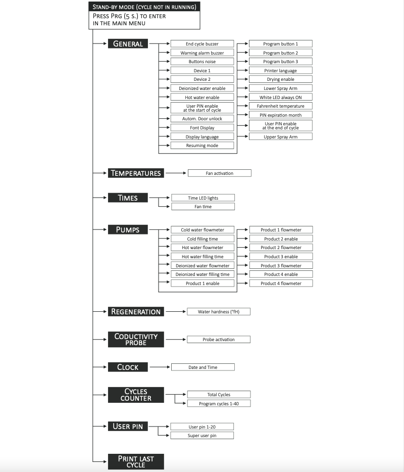
User settings menu
Start screen
 To access the settings menu the procedure is as follows: Open door -> PRG key for 5 seconds-> If the user and password are enabled, insert user password.
IMPORTANT NOTE! “User Pin Management” option on request.
The keys and their operation are shown below, contextualized according the menu in which you are located:
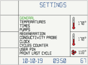
- Use P1 and P2 to navigate up and down the menu.
- Press START to access the entry of the menu selected. – Within the parameter, use the P1 and P2 keys to change the value of the highlighted parameter. – Press START to go to the next parameter.
- Press PRG to return to the previous menu.
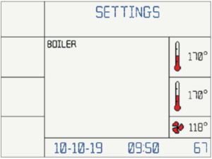
 The menu consists of two screens, the item, when selected, lights up:
Settings
 Language Setup
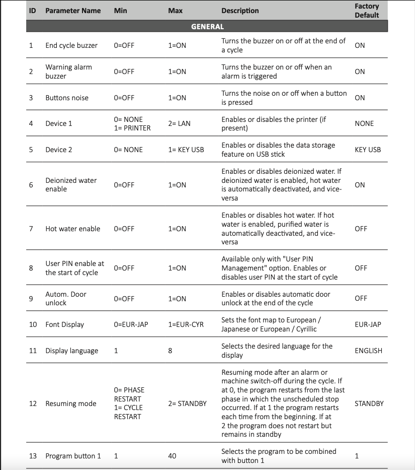
To change the display language, with the door open, press PRG for 5 seconds and enter the Super User password. Once the menu appears, press the START button under GENERAL. Scroll to the “Display Language” setting and select the desired language from those available.
USB key management
When the USB key is hooked up in the machine, the following message appears after a few seconds:
 When the USB key is removed from the machine, after a few seconds the following message appears.
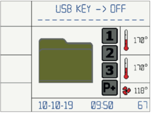 Use USB 2.0 only, system does not support USB 3.0.
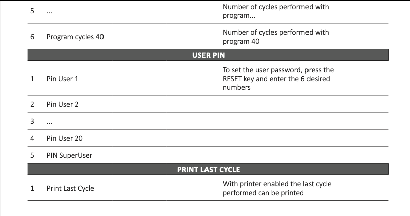
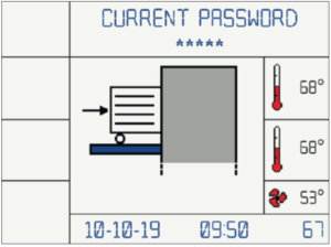
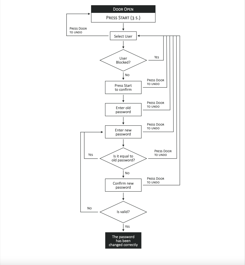
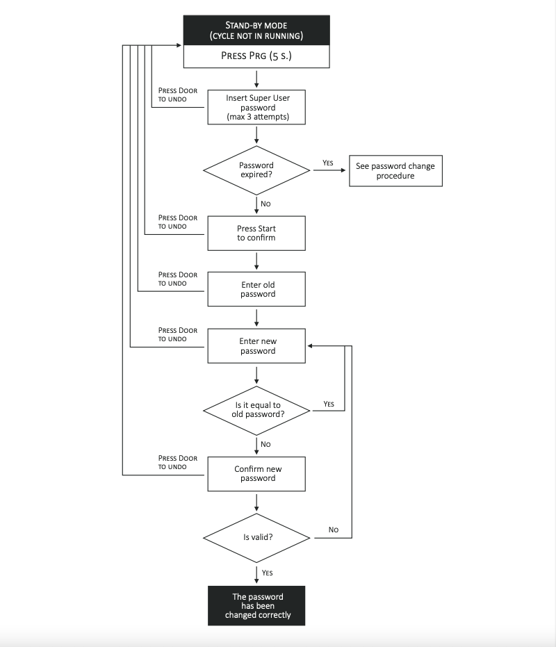
Procedure for password change
To generate the password use the keys P1, P2, P3, Reset, Start and Prg (See Fig. 15 for key description). Entering the password incorrectly three times in a row will cause the block of the user.
See Annex below display graphic
 Expiring passwords
User password
– Has a preset validity of 6 months, after the expiring date, it must be renewed. At first access it must be generated by the Super User. See Annex 12.3 for the procedure for password change. See Annex below for the procedure for user password setup for the Super User. This option is available if the USER PIN MANAGEMENT is enable.
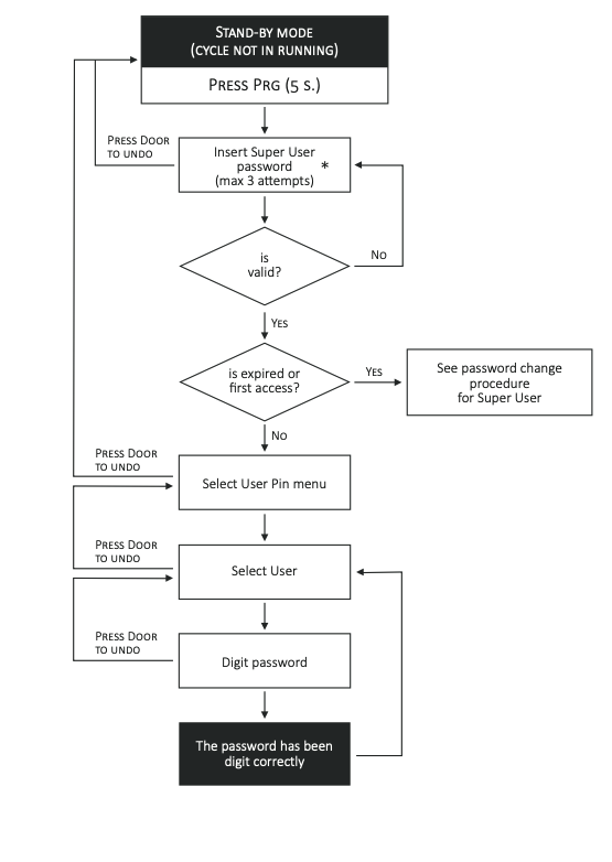
Super User password
– At the first access enter the password “111111”. As for the User, the Super User password has a preset validity of 6 months, after the expiring date, it must be renewed. See Annex below.
 Alarms
 Warnings
As always if you have any questions about this process or anything else please feel free to contact us and take advantage of our “FREE TECH SUPPORT.”
We also offer FREE VIRTUAL TECH SUPPORT to “See and Talk” with a “Real Time Live Technician” for any problems you may be in need of help with.
You can also use our “FREE MAINTENANCE PROGRAM”. Take the guesswork and worrying about what unit is due for maintenance and which maintenance cycle it is time for. We will keep track of all your autoclaves and let you know when it’s time for anything.