

Sterisil System G5 Installation and Operation Instructions Leave a comment
In this article, we’re going to show you how to properly install and operate your Sterisil G5 Dental Water Purification System.
In a previous article, we’ve shown you the Sterisil System G4. And just like the System G4, the Sterisil System G5 is a water distilling device that can constantly produce pure, quality water for your tabletop autoclaves. the G5 shares the same general benefits as the G4, however it goes beyond by taking the 6 step formula and merging it with advanced sterilization procedures. The Sterisil System G5 builds onto the 6-step process and adds on-board Class A ultraviolet disinfectant and integrated smart technology. The UV Disinfection eliminates up to 99.99% of all bacteria and viruses from the final product. And with integrated smart technology that allows for 24/7 monitoring, alerts and real-time data, this feature also allows for built-in troubleshooting when a maintenance alert appears. This combination of advanced features on this unit results in the System G5 being the most advanced dental water treatment system in the world.
Now that you have an idea of what this system can do, this article will show you how to install and operate your new Sterisil System G5.
And if you just want to talk to someone for any questions you may have, call our Free Tech Support at 704-966-1650 Option 3.
INSTALLATION
INITIAL INSTALLATION CONSIDERATIONS
IMPORTANT TO THE OWNER
We recommend a certified Sterisil® installer, professional technician, or plumber familiar with dental offices perform the installation since interfacing with a cold water line and drain is involved. He/She should be familiar with local plumbing codes and techniques for successful dental equipment installations.
Please keep the installation and maintenance manual on-hand for future reference. Ensure those responsible for operation and maintenance of the system is familiar with all details contained in this manual. Please return the warranty registration form via mail or register online at sterisil.com/warranty immediately upon installation. The Sterisil® System G5 unit requires power to produce water. In the event of a power outage, water will still be dispensed but will not be replenished until power is restored.
IMPORTANT TO THE INSTALLER
Please read the entire installation and maintenance manual and watch the installation video at sterisil.com/sterisil- system-g5 before proceeding with the installation and initial operation. Always follow local plumbing codes and municipal regulations. Familiarize yourself with the G5 drawings and diagrams included.
The G5 can be installed nearly anywhere in the typical dental, medical, lab, or hospital setting, typically near a faucet and sink. The system and tanks are designed to fit under a counter-top, but can be installed anywhere there is a quality, cold water supply and drain connection. Please locate the system serial label on the left panel of the unit or go to the settings tab on the touchscreen. Record the installation date on the warranty card. Please ensure you send in the warranty card or register online.
The initial set up can take up to 3–5 hours depending on customer specifications. Ensure the lengths of tubing provided will meet the needs of your specific configuration. All tubing cuts should be made at a right angle to the tubing itself. Be sure to inspect the ends for burrs before establishing a connection.
General Sterisil® System G5 Requirements
Minimum Pressure 60 PSI
Maximum Pressure 125 PSI
Minimum Temperature 45 °F
Maximum Temperature 100 °F
Plumbing Drain Standard sink or floor drain
Electrical and Internet Connectivity
Double outlet 110V AC, 3 amp, GFCI, within 5’ from System, Wi-Fi or Ethernet connection.
(Wi-Fi signal strength should be tested before installing the System.)
Bladder Tank Space
Tank 2G: 9”Dia x 12”H
Tank 4G: 12”Dia x 15”H
Tank 10G: 13”Dia x 21”H
Tank 14G: 15.25”Dia x 23”H
Internet Enabled Computer PC or Mac
INITIAL SETUP AND BASELINE REQUIREMENTS
For the system to fit functionally in its mounting, it will require at least:
- 27” in height
- 24” in length
- 11” in depth
These dimensions allows 2” of space on all sides of the system.
Direct Feed Specific Requirements
Dental Water Supply Tubing: (Customer Supplied):
- Centrally installed within the dental office, furthest chair should not exceed 50’ from the system
- Recommended use of PVC APEX A FIRE Rated tubing
- No brass or copper plumbing components may be used downstream of the system
Source Water Bypass: (Customer Supplied):
- A source water bypass should be installed by a plumber or technician to bypass the System if necessary.
Bottle Fill Installation
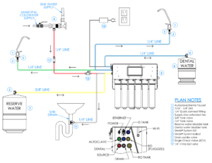 Direct Feed Installation
PHASE 1: UNPACKING AND INVENTORY
Carefully unpack the contents of the boxes. One box will include the Sterisil® System G5. The second box will contain the installation manual, warranty registration card, and assorted bags containing other needed items for installation, including mounting system for static, slides, and articulating mount. Each water storage tank will be shipped separately.
–VERIFY THERE WAS NO DAMAGE DURING SHIPMENT. IF DAMAGE IS EVIDENT, CONTACT THE SHIPPING COMPANY IMMEDIATELY–
TOOLS
Tools required for installation:
- Phillips head screwdriver
- Standard open end/box end wrenches ranging from 1⁄2” to 3⁄4” • Small to medium size adjustable wrench
- Standard hex key set
- Box knife
- Hand drill
- Phillips driver bits
- Universal drill bits: sizes 1/8” to 1⁄2” standard
- Level
- Schrader valved pressure gauge
- Low volume air pump
–INVENTORY ITEMS MAY VARY DEPENDING ON SYSTEM SELECTION AND SPECIFIC PARAMETERS.–
BOX 1: UNIT
Sterisil® System G5
BOX 2: ACCESSORIES
10 ft 3/8” tubing
20 ft 1/4” tubing
System power supply
Autoclave faucet
Dental faucet
Cartridges (Stage 1, 2, 3, 4 [x2], 5)
Blank Cartridge and clip
System mount (Static, Sliding or Articulating) Bag A
Bag B.1
Bag B.2
Bag B.3
Bag C
Bag D
Bag E
BOX 3:
Dental Water Storage Tank
BOX 4:
RO Water Storage Tank
PHASE 2: MOUNTING AND PERIPHERAL COMPONENTS
 CONSIDERATIONS PRIOR TO MOUNTING
The location of your Sterisil® System G5 needs the following considerations:
- Distance to the water supply
- Leave enough slack in tubing to account for mounting configurations
- Accessibility to touchscreen
- UV light replacement, allow for 12” for clearance
- Cartridge clearance
- Distance to the 2 electrical outlets
- Drain location for the line
- Placement location for the bladder tanks
- Type of system mounting device: Static, Sliding or Accordion mount
- Strength of wall or cabinet for installation
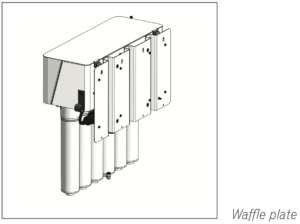 The G5 can be mounted in 1 of 3 ways; a static wall mount, a slide mount inside a cabinet, or an articulating wall mount. The rear waffle mounting plate affixed to the unit itself will serve as a mounting point for all 3 methods of mounting the system. Sterisil recommends anchoring the system into a wall stud. The EZ-toggle anchors should only be used when drilling into drywall.
STATIC MOUNT
Affixing the Static Plate to the Wall
- Identify the slotted holes on the plate. These slots will be used to mount the plate to the wall.
- The static plate is symmetrical so any side can be up.
- Mock up your static mounting plate in the desired location. Ensure the plate is level and mark your holes.
- Drill and affix the plate to the wall.
- Verify the static plate is level.
Securing the G5 to the Static Mounting Plate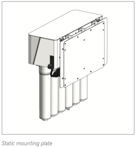
- Take 4 socket cap screws and screw them into the top row of the static mount. Do not fully tighten these screws.
- Take the unit (waffle plate already affixed) and line the key slots on the back of the waffle plate up with the socket cap screws. Slot the system downward so the unit hangs on the screws.
- Screw the remaining socket cap screws into the bottom row of threaded holes.
- Use your provided 5/32” Allen wrench provided to tighten the top and bottom rows.
- Verify the unit is level.
SLIDE MOUNT
The Sterisil® System G5 will come with the slides affixed in the correct direction for proper maintenance. Please consider the orientation of the slides and affixing the slide mount to the wall mounting plate before you start.
Affixing the Slide Mount to the Wall 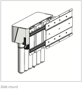
- Mark the holes on the slide mounting plate.
- Screw the mounting plate to the wall and ensure it is level.
Securing the G5 to the Slide Mount
- Take the system and line up the rails on the back of the waffle plate to the slides on the mounting plate. Slide the unit until you hear the rails snap into place.
- Verify it is level.
ARTICULATING MOUNT
Affixing the Articulating Mount to the Wall 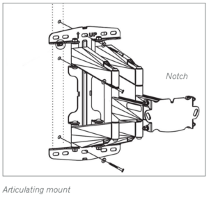
- Use articulating mount hardware (included in package).
- Place the mount against the wall with the “up” arrow facing the ceiling. Ensure the mount is level and mark your holes.
- Pilot holes are either 3/8” or 9/64”.
- Affix the mount to the wall with the appropriate combination of hardware for your mounting surface.
- Confirm it is level.
Securing the G5 to the Articulating Mount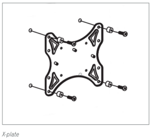
- The system will come with the waffle plate attached. Tack the X-plate to the back of the waffle plate. You may need to place the unit on the front face to accomplish this. Please be mindful of the touchscreen if you do so. Use the packing foam to avoid damage to the touchscreen.
- Mount the X-plate to the waffle plate using the bolts and washers. Make sure the “up” arrow is facing the top of the system.
- You will notice a notch in the upper middle portion of the X-plate. Tighten a screw nut to this notch.
- Mount the system to the articulating mount by hanging the top screw nut affixed to the X-plate in the notch on the arm mount.
- Fasten the entire assembly to the wall mount with the two remaining nuts. Be sure the unit is level and tighten with 1/2” wrench.
- Properly orient the unit and tighten the forward tilt nuts once system is completely level.
PERIPHERAL COMPONENTS
Peripheral Components – No more than 50 feet from the system.
G5 POWER ADAPTER
- Select location within 6 feet of the outlet. Ensure there is no tension on the cable.
- If you choose to mount the power adapter on the wall, use hardware straps provided.
WATER STORAGE TANKS – (BAG C)
Storage tank sizes may differ with customer specifications and needs. Note: tank sizes will vary depending on Stage 5 selection or pre-install requirements. As a default, the RO tank will be the larger of the two. Storage tanks must be mounted within 50 feet of the system to maintain optimal water pressure. Set storage tanks in desired locations. A common location is under a sterilization center sink.
- Wrap the threads with Teflon tape (included) on each bladder tank. Install the 3/8” valve and hand tighten it to the larger RO tank. Do not over tighten this valve.
- Repeat this process with the 1/4” valve for the Dental Water Tank.
- Ensure the pressure of the tanks is between 8–10 psi Schrader valved pressure gauge.
FAUCET(S) INSTALLATION
The bottle fill configuration includes a white Autoclave Faucet and a chrome Dental Water Faucet. Dental water is always plumbed to the chrome faucet. Typical mounting location is on a counter-top extended over a sink.

Direct feed systems only use the white Autoclave Faucet. Dental water is fed directly to the dental unit hand pieces.
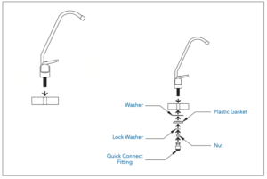
COUNTER-TOP MOUNT
Faucet assembly instructions are located on the back of the faucet box.
- Do not use the compression fittings provided. Instead use the provided push-fit connect.
- Drill 5/8” hole at the desired location.
- Place the faucet through the hole and mount using the hardware (included).
- Wrap the thread with thread tape prior to install.
- Place the under-sink mounting washer, and install the nut (included in box) and hand tighten.
PHASE 3: CARTRIDGES
- Remove the yellow cap from the top of the cartridges and write the date with a permanent marker.
- Start by inserting the cartridges from left to right beginning with Stage 1.
Please note there are two Stage 4 Cartridges. They will both be positioned interchangeably in ports 4 and 5. - Once all cartridges are installed, remove the brine plug from the bottom of the Stage 3 Cartridge.
- Insert the white brine tube into the bottom of Stage 3.
- Mount the Blank Cartridge clip on the wall near the system and place the Blank Cartridge in the clip.
Please note the Blank Cartridge is essential for trouble shooting possible blockages inside the system.
PHASE 4: SOURCE WATER AND TUBING
Ensure the source water to the Sterisil® System G5 remains closed until the procedure calls for it to be turned on.
SOURCE WATER CONNECTION
Supply Tee
- Turn off the water on the municipal supply line. For now the main valve will remained closed.
- Remove the existing hose, wrap the threads with thread tape, and install the supply tee on the cold water supply. Tighten the tee with a wrench. Hot water should not be used to feed the system.
TUBING CONNECTIONS
To make a connection with quick connect fittings, you will simply push the tubing into the fitting until it stops. When making cuts, be sure to cut at a right angle to the tubing itself, and inspect the ends for burrs. Be sure to factor any movement in the system into the tubing length so as to not put tension on ports or components.
Source water (Supply Tee to Source Port)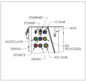
(Red fitting collar):
- Insert the white 1/4” tubing into the supply tee. The other end of this tubing will run to the “SOURCE” port on the side of the system.
- Cut and install the Single Check Valve (SCV) on this line. (Bag D)
- Cut and install a 1/4” inline ball valve.
Dental Port: (Blue fitting indicator):
- Run a 1/4” line from the blue “DENTAL” port to the chrome Dental Water Faucet.
- Direct Feed System: Run a 1/4” line from the blue “DENTAL” port on the system to the customer supplied dental water supply line that connects to the dental chairs.
D Tank Port (Blue fitting Indicator):
- Run 1/4” tubing from the blue “DENTAL” port on the system to the 1/4” Tank Ball Valve on the smaller dental water storage tank.
Autoclave Port (Green fitting indicator):
- Run 1/4” tubing from the green “AUTOCLAVE” port on the system to the white Autoclave Faucet.
Drain Port (Black fitting indicator): (Bag D)
Run a 1/4” line from the black “DRAIN” port to the Drain Saddle Valve (DSV).
Note: If you have a floor drain that is accessible you can always run tubing straight from the black “DRAIN” port on the system to the floor drain. If not, you will need to install the drain saddle valve on an existing drain pipe.
Drain saddle valve: 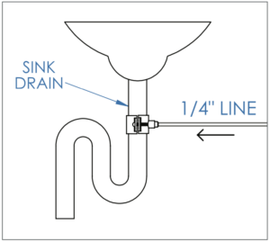
- Start by marking the drain pipe where you intend to drill your 1/4” hole. The DSV will need to be before or after the peatrap.
- Attach the gasket and mount the saddle valve with the provided nuts and bolts to the drain pipe.
- Once the DSV is properly mounted remove the gray collet from the hole.
- Drill through the hole into the drain pipe.
- When you drill the hole, be sure not to drill through the other side of the drain pipe.
- Clear any metal shavings from the hole, then reinsert the collet.
- Run 1/4” line from the black “DRAIN” port on the system to the DSV.
RO Tank Port (Yellow fitting indicator):
- Run a 3/8” line from the yellow “RO TANK” port on the system to the 3/8” Tank Ball Valve on the RO Water Storage Tank.
RO port (Yellow fitting indicator):
- If no auxiliary RO water will be used then this yellow RO port should remain plugged.
PHASE 5: POWERING UP, PROGRAMMING THE TOUCHSCREEN AND FILLING THE TANKS
POWERING UP
- Plug in the G5. The touchscreen will power on, and you will be brought to the home screen.
PROGRAMING THE TOUCHSCREEN
(All programing steps below are represented in the installation video at sterisil.com/sterisil-system-g5.)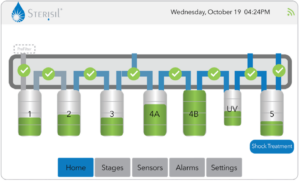
- Bring up the details view by touching either the desired Stage number from the “Home” screen or select the “Stages” tab from
the bottom row. - Stage 1’s lifespan is for 364 days. If the counter is not reading 364 days you will select “Replace component,” select Stage 1 from the drop-down menu and hit replace.
- Stage 2’s lifespan is based on liters processed and is effective up to 9,463L. If the counter is not reading 9,463L, you will select “Replace component,” select Stage 2 from the drop-down menu and hit replace.
- Stage 3’s lifespan is based on either a 364 day count or the TDS quality of water coming off it. If the counter on Stage 3 is not reading 364 days you will select “Replace component,” select Stage 3 from the drop-down menu and hit replace.
- Stage 4’s lifespan is a function of water quality. The alarm will sound if water quality reaches above 10ppm on the lead cartridge. No resetting is required upon initial installation.
- The UV light’s life is based on both light intensity and a 364 day count. To reset the light monitor, select the “UV lamp” tab on the bottom row and select replace component.
- Stage 5’s lifespan is based on a liter count. Each Stage 5 is marked with its liter capacity. From the Stage 5 details screen verify that your maximum capacity matches the capacity printed on the cartridge. If not, reset the count to the correct number.
FILLING THE TANKS
At this point both storage tank valves should be closed: meaning the ball valve knob is turned perpendicular with the tubing going in.
- Open the RO and Dental Storage Tanks by turning the tank ball valve knob in line with the tubing.
Confirm source water pressure is above 65 PSI and below 125 PSI.
- Open the Source Water Valve at your municipal supply.
- The RO and dental tanks will slowly begin to fill. Allow for 8–12 hours for tanks to completely fill.
- Check connections and ensure there are no leaks.
OPERATIONAL TEST
- Allow the RO and Dental Water Tanks to fill completely before performing the operational test.
- After four hours, open the valve at the white Autoclave Faucet, and start running water. At this point you should be looking for leaks anywhere in the system and connecting tubing. Once you have water at the faucet and confirmed there are no leaks, run for 2–3 minutes, then close the faucet.
- Repeat this process for the chrome Dental Water Faucet.
Direct Feed System: Run handpiece water at the furthest chair from the system. Check for leaks. Note: You will not have adequate water pressure until the Dental Tank has filled.
PROGRAMMING
CONNECTING TO THE NETWORK
- From the “Home” tab on the touchscreen, you will select the “Settings” tab.
- Select the “Network” button.
- Go to “Network interface,” and select a method of connection from the drop-down menu.
- Select “Scan” and then select “SSID” to populate the list of possible networks.
- From the list, select the appropriate network and enter in the password if necessary and hit “Connect”.
- Once you are connected you will want to select “Save setting.”
- The Sterisil® System G5 must be on the same Wi-Fi connection as the computer.
PC APP
The PC app is essential to maximizing the potential of the G5. The app can aggregate data from multiple systems to be accessed on demand.
- To install the PC app, go to sterisil.com/sterisil-system-g5. Locate app under the docs tab.
- Follow the instructions to install.
As always if you have any questions about this process or anything else please feel free to contact us and take advantage of our “FREE TECH SUPPORT.”
We also offer FREE VIRTUAL TECH SUPPORT to “See and Talk” with a “Real Time Live Technician” for any problems you may be in need of help with.
You can also use our “FREE MAINTENANCE PROGRAM”. Take the guesswork and worrying about what unit is due for maintenance and which maintenance cycle it is time for. We will keep track of all your autoclaves and let you know when it’s time for anything.