

Sterisil System G4 Installation and Operation Leave a comment
In previous articles on its installation, operation and maintenance, we’ve talked about the Sterisil AC+ System. The AC+ System is a water distilling device that can constantly produce pure, quality water for your tabletop autoclaves. But Sterisil didn’t stop there, and now they’re back to bring you the Sterisil System G4. The G4 is Sterisil’s newcomer; an EPA registered water purification device with a 6 step purification process to ensure that your autoclave and dental water is as safe and pure as possible for patients and staff alike.
As opposed to the 4-step process of the AC+, the 6-step G4 System includes new purification and disinfection features like reverse osmosis, deionization, Class B ultraviolet (UV) disinfection, and Sterisil’s proprietary residual silver disinfectant. And the unit is also completely scalable to fit your office needs. No more worrying about using too little for too big a task just for conservation purposes. Sterisil’s Dental Waterline Compliance Specialists have you covered to get you the apt amount of water for your facility’s uses, whether it’s 1 to 100+ chairs, it’s no problem at all.
And to top it off, your mind can be put at ease without the hassle of remembering maintenance times and schedules on your own. The Sterisil G4 system comes equipped with a multitude of sensors, monitors and indicators to let you know when it’s time to take action. Both visual and audible warnings are on cue for when a problem arises, so there’s no chance to miss one or the other.
Now that you have an idea of what this system can do, this article will show you how to install and operate your new Sterisil System G4.
And if you just want to talk to someone for any questions you may have, call our Free Tech Support at 704-966-1650 Option 3.
Before You Begin
Initial Installation Considerations

IMPORTANT: Sections marked with the red triangle icon contain information that must be taken into consideration before installation.

BOTTLE FILL AND DIRECT FEED COMPARISON: The Sterisil® System G4 can be configured for independant bottle reservoirs or municipal direct feed depending on the office configuration. Throughout this manual, designated sections specific to the direct feed configuration will be highlighted in blue with the blue triangle icon. Pay specific attention to the plumbing of dental water with direct feed systems as they are significantly different from their bottle fill counterparts.
Important to the Owner
We recommend a certified Sterisil® installer, professional technician, or plumber familiar with dental offices perform the installation because interfacing with a cold water line and drain is involved. He/ she should be familiar with local plumbing codes and techniques for successful dental equipment installations.
Please keep the installation and maintenance manual on hand for future reference. Ensure those responsible for operation and maintenance of the system is familiar with all details contained in this manual. Please return the warranty registration form via mail or register online at sterisil.com/warranty immediately upon installation.
Important to the Installer
Please read the entire installation and maintenance manual before proceeding with the installation and initial operation. Always follow local plumbing codes and municipal regulations. Familiarize yourself with the G4 drawings and diagrams included.
The G4 can be installed nearly anywhere in the typical dental, medical, lab, or hospital setting, typically near a faucet and sink. The system and tanks are designed to fit under a counter-top, but can be installed anywhere there is a quality, cold water supply and drain connection. Please locate the system’s serial number on the left panel of the unit. Record the installation date on the warranty card. Please ensure you send in the warranty card or register online.
The initial set up can take up to 3–5 hours depending on customer specifications. Ensure the lengths of tubing provided will meet the needs of your specific configuration. All tubing cuts should be made at a right angle to the tubing itself. Be sure to inspect the ends for burrs before establishing a connection.
Specifications
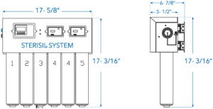
INITIAL SETUP AND BASELINE REQUIREMENTS: For the system to fit functionally in its mounting, it will require at least:
-20” in length – 9” in width – 20” in height- These dimensions allow for 2” of space on all sides of the system.
Direct Feed Specific Requirements (Customer Supplied):
- Centrally installed within the dental office, the furthest chair should not exceed 50’ from the system.
- No brass or copper plumbing components may be used downstream of the system.
- Recommended use of PVC APEX A FIRE Rated tubing for delivery of dental water.
- Source water bypass should be installed by a plumber or technician to bypass the system if necessary.
Sterisil System G4 Specifications
Minimum Pressure
65 PSI
Maximum Pressure
85 PSI
Minimum Temperature
45° F
Maximum Temperature
100° F
Faucets (2) Sink with space for two faucets
Plumbing Drain Standard sink or floor drain
Electrical Outlets (1) Quad outlet 110V AC, 3 amp, GFCI, within 3' from system
Mounting Space System: 20"W x 20"H x 9"D
Bladder Tank Space Tank 2G: 12"H x 9”Dia
Tank 4G: 15"H x 12"Dia
Tank 10G: 21"H x 13"Dia
Tank 14G: 23"H x 15.25"Dia
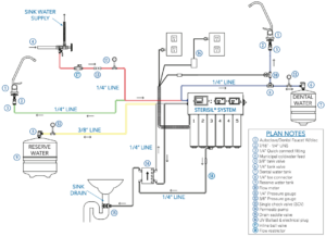
Bottle Fill Installation
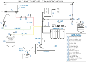
Direct Feed Installation
Phase 1: Unpacking and Inventory
Carefully unpack the contents of the boxes. The standard Sterisil® System G4 configuration is shipped in three boxes. One box will include the G4 along with the installation manual, warranty registration card, system mount, and assorted bags containing other needed items for installation. Each water storage tank will be shipped separately.
VERIFY THERE WAS NO DAMAGE DURING SHIPMENT. IF DAMAGE IS EVIDENT, CONTACT THE SHIPPING COMPANY IMMEDIATELY.
TOOLS
Tools required for this installation:
- Phillips head screwdriver
- Standard open end/box end wrenches ranging from 1⁄2” to 3⁄4”
- Small to medium size adjustable wrench
- Standard hex key set
- Box knife
- Hand drill
- Phillips driver bits
- Universal drill bits: sizes 1/8” to 1⁄2” standard
- Level
- Schrader valved pressure gauge
- Low volume air pump
INVENTORY ITEMS MAY VARY DEPENDING ON SYSTEM SELECTION AND SPECIFIC PARAMETERS.
BOX 1:
- Sterisil® System G4
- System mount (slide or hinged)
- Bag: (Manual, packing list, faucet stickers, tank stickers and warranty card)
- 10 ft 3/8” tubing
- 40 ft 1/4” tubing
- Autoclave Faucet (white) and Dental Faucet (chrome) w/ 1/4” to 7/16” faucet connectors
- Cartridges (Stage 1, 2, 3, 4 [x2], 5)
- Permeate Pump
- Blank Cartridge, clip and mounting screws
- UV Light transformer
- Large bag: Drain Saddle Valve, thread tape, Permeate Pump clip, 1/4” pressure gauge x2, 3/8” pressure gauge, Flow Sensor, Flow Restrictor, modular couplers, stem elbow x3, Dental Autoclave Discs, cables and RJ-12 connectors.
- Small bag: #10×1” mounting screws x8, sheet rock plastic anchors x8, supply tee, 1/4” union tee, 1/4” Tank Ball Valve, 3/8” Tank Ball Valve, Inline Ball Valve and Single Check Valve.
BOX 2:
- Dental Water Storage Tank
BOX 3:
- Reserve Water Storage Tank
PHASE 2: MOUNTING AND PERIPHERAL COMPONENTS
CONSIDERATIONS PRIOR TO MOUNTING:
The location of your Sterisil® System G4 needs the following considerations:
- Distance to the water supply
- Leave enough slack in tubing to account for mounting configurations
- Accessibility to digital monitors
- UV Light replacement, allow 12” for clearance
- Cartridge clearance
- Distance to the electrical outlets
- Drain location for the brine line
- Placement location for the storage tanks
- Type of system mounting device: Slide or Hinged mount
SLIDE MOUNT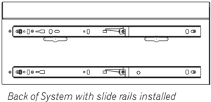
The system will come with the slides affixed in the correct direction for proper maintenance. Please consider the orientation of the slides and affixing the slide mount to the wall mounting plate before you start.
Affixing the Slide Mount to the Wall-
- Remove the system off of the slide mount.
- Take your slide mounting plate and mark your holes.
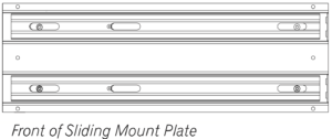
- Screw the mounting plate to the wall and ensure it is level.
Securing the G4 to the Slide Mount-
- Take the system and line up the rails on the back of the system plate to the slides on the mounting plate. Slide the unit until you hear the rails snap into place.
- Verify it is level.
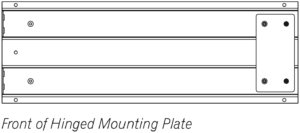
HINGED MOUNT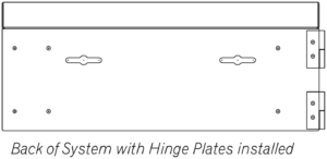
The system will come with the hinges affixed in the correct direction for proper maintenance. Please consider the orientation of the hinges and affixing the hinged mount to the wall mounting plate before you start.
Affixing the Hinged Mount to the Wall-
- Remove the system from the mount.
- Take your hinged mounting plate and mark your holes.
- Screw the mounting plate to the wall and ensure it is level.
Securing the G4 to the Hinged Mount-
- Take the system hinges and affix them to the side of the mounting plate. Push to confirm connection.
- Verify it is level.
PERIPHERAL COMPONENTS
Peripheral Components – No more than 50 feet from the system.
WATER STORAGE TANKS
Storage tank sizes may differ with customer specifications and needs. Note: tank sizes will vary depending on Stage 5 selection or pre-install requirements. As a default, the Reserve Tank will be the larger of the two. Storage tanks must be mounted within 50 feet of the system to maintain optimal water pressure. Set storage tanks in desired locations. A common location is under a sterilization center sink.
- Wrap the threads on top of the tanks with thread tape (included) on each storage tank. Install the 3/8” valve and hand tighten it to the larger Reserve Tank. Do not over tighten this valve.
- Repeat this process with the 1/4” valve for the Dental Water Tank.
- Ensure the pressure of the tanks is between 8–10 psi using a Schrader valved pressure gauge.
FAUCET(S) INSTALLATION
The bottle fill configuration includes a white Autoclave Faucet and a chrome Dental Faucet. Dental water is always plumbed to the chrome faucet. Typical mounting location is on a counter-top extended over a sink.
Direct feed systems only use the white Autoclave Faucet. Dental water is fed directly to the dental unit hand pieces.
COUNTER-TOP MOUNT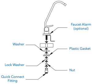
Faucet assembly instructions are located on the back of the faucet box.
- Do not use the compression fittings provided. Instead, use the provided push-fit 1/4” to 7/16” faucet connectors.
- Drill a 5/8” hole at the desired location.
- Place the faucet through the hole and mount using the hardware (included).
- Place the under-sink mounting washer, plastic gasket, lock washer, and install the nut (included in box) and hand tighten.
- Wrap the threads with thread tape, and install faucet connectors.
PHASE 3: CARTRIDGES
- Remove the yellow cap from the top of the cartridges, and write the install date with a permanent marker.
- Start by inserting the cartridges from left to right beginning with Stage 1. Please note, there are two Stage 4 Cartridges. They will both be positioned interchangeably in ports 4 and 5.
- Once all cartridges are installed, remove the brine plug from the bottom of the Stage 3 Cartridge.
- Install the stem elbow.
- The bottom of Stage 3 will be used in future installation steps.
- Mount the Blank Cartridge clip on the wall near the system and place the Blank Cartridge in the clip.
- Please note, the Blank Cartridge is essential for troubleshooting possible blockages inside the system.
PHASE 4: SOURCE WATER AND TUBING
Ensure the source water to the Sterisil® System G4 remains closed until the procedure calls for it to be turned on.
SOURCE WATER CONNECTION
Supply Tee
- Turn off the water on the municipal supply line.
- Remove the existing hose, wrap the threads with thread tape, and install the supply tee on the cold water supply. Tighten the tee with a wrench. Hot water should not be used to feed the Sterisil® System G4. For now the main valve will remained closed.
![]() TUBING CONNECTIONS
TUBING CONNECTIONS 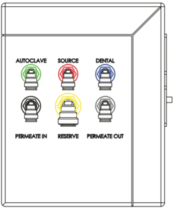
To make a connection with quick connect fittings, simply push the tubing into the fitting until it stops. When making cuts, be sure to cut at a right angle to the tubing itself, and inspect the ends for burrs. Be sure to factor any movement in the system into the tubing length so as to not put tension on ports or components.
Source Water: (Supply Tee to Source Port): (Red fitting indicator)
- Insert the white 1/4” tubing into the supply tee. The other end of this tubing will run to the “SOURCE” port on the side of the system.
- Cut and install a 1/4” Inline Ball Valve.
- Cut and install Single Check Valve (SCV) on this line.
Dental Port: (Blue fitting indicator)
- Run 1/4” tubing from “DENTAL” port on the system to the 1/4” union tee.
- Run tubing from 1/4” union tee to the 1/4” tank ball valve on the Dental Water Storage Tank.
- Cut and insert 1/4” pressure gauge along tubing between connections, as close to the tank as possible.
- On the other side of the 1/4” union tee, run tubing to the chrome Dental Water Faucet.
- Direct Feed System: Run a 1/4” line from the union tee to the customer provided dental water supply line that connects to the dental chairs.
- Cut and insert the Flow Sensor between the faucet and 1/4” union tee junction. Ensure two stem elbows are installed on the Flow Sensor.
-
Cut and insert the Single Check Valve between flow meter and the dental water supply line. Ensure arrow is pointed towards the dental water supply line.
Autoclave Port: (Green fitting indicator)
- Run 1/4” tubing from the green “AUTOCLAVE” port on the system to the white Autoclave Faucet.
Peripheral Components:
IMPORTANT: The Permeate Pump must be mounted with the long arrow pointing up. The Permeate Pump will not function properly if positioned sideways or upside down.
- Run 1/4” tubing from bottom of Stage 3 to “BRINE IN” on the Permeate Pump.
- Cut and insert the Flow Restrictor with the arrow pointing towards the Permeate Pump.
- Run 1/4” tubing from “BRINE OUT” on the Permeate Pump to Drain Saddle Valve (DSV).
- Note: If you have a floor drain that is accessible, you can always run tubing straight from the “BRINE OUT” port on the pump to the floor drain. If not, you will need to install the DSV on an existing drain pipe. Ensure tubing is secured into the drain.
- Run 1/4” tubing from “PERMEATE IN” on the Permeate Pump to black “PERMEATE IN” port on the system.
- Run 1/4” tubing from “PERMEATE OUT” on the Permeate Pump to grey “PERMEATE OUT” port on the system.
Drain Saddle Valve (DSV): 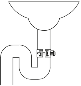
- Start by marking the drain pipe where you intend to drill your 1/4” hole. The DSV will need to be before or after the peatrap.
- Attach the gasket and mount the saddle valve with the provided nuts and bolts to the drain pipe.
- Once the DSV is properly mounted remove the gray collet from the hole.
- Drill through the hole into the drain pipe.
- When you drill the hole, be sure not to drill through the other side of the drain pipe.
- Clear any metal shavings from the hole, then reinsert the collet.
- Run 1/4” line from “BRINE OUT” on the Permeate Pump to the DSV.
Reserve Port: (Yellow fitting indicator)
- Run a 3/8” line from the yellow “RESERVE” port on the system to the 3/8” Tank Ball Valve on the Reserve Water Storage Tank.
- Cut and insert the 3/8” pressure gauge, as close to the tank as possible.
PHASE 5: ELECTRICAL AND OPERATION TEST
ELECTRICAL
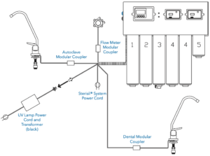
Connect all flat, 4-wire data standard power cords using color code and labels attached to the wires.
-
Direct Feed System will not include a chrome Dental Faucet, Dental Modular Coupler or Data Cable.
OPERATIONAL TEST
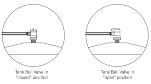
At this point, both Storage Tank Valves should be closed; meaning the ball valve knob is turned perpendicular with the tubing going in.
- Plug in the UV Light Transformer and verify the light is functional. There will be a slight blue/purple glow.
- Open the Source Water Valve at your municipal supply.
- Confirm source water pressure is above 65 PSI and below 85 PSI.
- Leave both tanks closed.
- Turn on the Autoclave Faucet, and wait for water. Check for leaks, then turn off the faucet.
- Turn on the Dental Faucet, and look for a thin stream of water. Check for leaks, then turn off the
faucet. - Open the Reserve and Dental Storage Tanks by turning the tank ball valve knob in line with the tubing. Tanks will slowly begin to fill. Allow at least four hours for pressurization and 8–12 hours for tanks to completely fill.
- After four hours, open the valve at the white Autoclave Faucet, and start running water. At this point, you should be looking for leaks anywhere in the system and connecting tubing. Once you have water at the faucet and confirmed there are no leaks, run for 2–3 minutes, then close the faucet.
- Repeat this process for the chrome Dental Water Faucet.
-
Direct Feed System: Run handpiece water at the furthest chair from the system. Check for leaks. Note: you will not have adequate water pressure until the Dental Tank has filled.
- Check RO Quality Monitor and DI Quality Monitor readings.
- Ensure the Filter Monitor is set properly.
- Sterisil® recommends all waterlines be shocked by a plumber or technician before daily use.
If you have any questions about this procedure or any other Sterisil System G4 Tech Issues please contact us and let us help.
As always if you have any questions about this process or anything else please feel free to contact us and take advantage of our “FREE TECH SUPPORT.”
We also offer FREE VIRTUAL TECH SUPPORT to “See and Talk” with a “Real Time Live Technician” for any problems you may be in need of help with.
You can also use our “FREE MAINTENANCE PROGRAM”. Take the guesswork and worrying about what unit is due for maintenance and which maintenance cycle it is time for. We will keep track of all your autoclaves and let you know when it’s time for anything.