Solmetex NXT DryVac Installation Guide
We released an article going over one of Solmetex’s new products that we now carry. Their NXT DryVac Tankless Dry Vaccum. An innovative approach that’ll change the way we look at dental water line vacuum systems. And in line with our usual practice, we released an overview of the unit which you can find here, and learn more about Solmetex and their fascinating new device. So now we move on to our guides, starting here, with the NXT DryVac installation guide. These instructions are from the manufacturers themselves, to ensure your installation process is done properly.
Installation Guidelines
The NXT DryVac suction system (tankless dry vacuum system) is designed to be installed only in dry, adequately ventilated rooms.
![]() Warning: Use of this equipment in areas subject to explosive and fire hazards is not permitted.
Warning: Use of this equipment in areas subject to explosive and fire hazards is not permitted.
Temperature and Ventilation
- The operating temperature ranges from between +40° F (+10° C) and +104° F (+35° C). The relative humidity must not exceed 70%.
- The storage and transport temperature ranges from between +32° F (+0° C) and +158° F (70°C). The relative humidity must not exceed 80%.
- In case of a room temperature of more than +95° F (+35° C), a fan must be installed for additional ventilation. An exhaust fan is necessary if room temperature is not maintained by other methods.
- Adequate forced ventilation must be provided across the unit by placing an appropriate exhaust fan opposite an equivalent air intake vent . The fan should be placed higher than the associated intake vent.
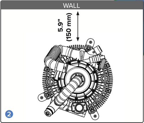 2. See Illustration
When the NXT DryVac suction system (tankless dry vacuum system) is installed, the connection side must be placed at least 5.9“ (150 mm) from the wall so that the hoses can be connected.
- Installation can be on the same level as the dental units, in a side room or one floor lower.
- In order to avoid vibrations, the suction system must be installed on a firm base.
- The maximum altitude is 9843 feet (3000 m).
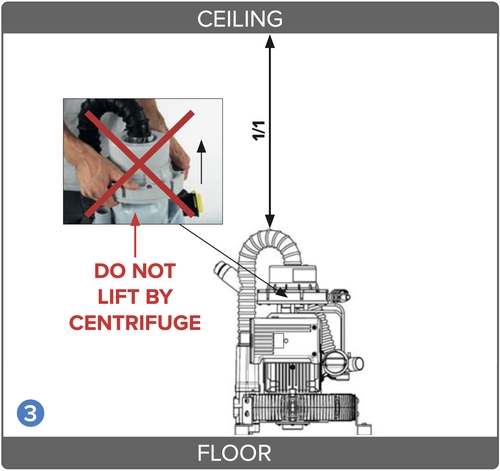
3. See Illustration
The front of the device must be easily accessible. There must be clear space of approx. 2“ (50 mm) around the device to guarantee adequate air circulation.
Warning: Do not lift the device by centrifuge!
Warning: To avoid loss of suction, the device must not be switched off at the office main switch or the protection switch of the control box, while suction is in use.
 See Illustration 1
- Only flexible spiral hoses, rated for vacuum, made from PVC or equivalent materials may be used.
- Connections to the NXT DryVac central suction system (tankless dry vacuum system) must be made by flexible hoses and be as short as possible.
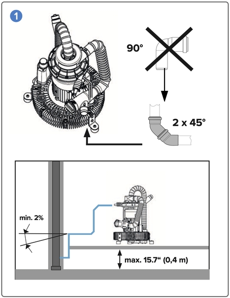
- A pipe diameter of 1 1/2“ (40mm) is recommended. Avoid right-angle bends in order not to lose suction power (dry vacuum power) (recommendation: 2 x 45° degree bends). Use only 45° degree elbows to make turns in the main line.
- Discharge pipes must meet applicable local codes.
- Waste water must be allowed to drain off freely without any backup. Waste water pipes must have a hydraulic gradient of at least 2% slope.
Exhaust Air
- The air must be discharged out-of-doors. For reasons of hygiene and to avoid noise pollution, it is recommended that the outgoing air connection is fitted with a bio-filter.
- The diameter of the discharged air connection must be equal to or bigger than the diameter of the suction connection. Use metal pipe. Do not make a trap in the exhaust vent piping. Do not use 90° fittings. Connection between the pump and exhaust vent piping is typically made via the supplied 2-inch black heat resisting hose.
Exhaust Vent Protection
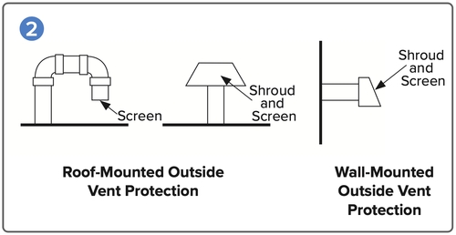 If the exhaust piping is venting to the outside of the building, precautions must be taken to protect the equipment room from weather elements and animal intrusion.
 Exhaust air: condensate water backflow
A self-closing flap or a fine-meshed grid must be installed at the air outlet to prevent particles or small animals from entering.
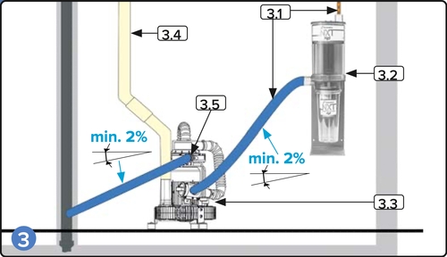
It must be ensured that no condensate water can run from the exhaust air to the suction machine. The exhaust air must be lead outside and equipped with a condensate collector.
- 3.1 Condensate collector
- 3.2 Heat resistant exhaust air hose (flexible)
- 3.3 Condensate water outlet (1⁄4“ tubing x 5’ long)
- 3.4 Vacuum suction inlet
- 3.5 Waste water outlet hose
- 3.6 Vacuum gauge
- 3.7 Inlet adapter
- 3.8 Vacuum inlet coupling
Hose Connections
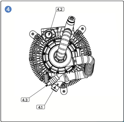
- 4.1 Connection for the suction hose (from the dental units): 1 1⁄2“ (40 mm) diameter
- 4.2 Connection for exhaust air: 2“ (50 mm) diameter
- 4.3 Connection for waste water (clean water discharge): 5⁄8“ (15 mm) diameter
Pipe and Hose Installation
Attention:
- Any pipe or hose used must be vacuum tight and resistant to all chemicals normally used in a dental practice (e.g. HT discharge pipes made from PP, PVC-C, PVC-U, PE-HD).
- All hose connections must be secured with hose clamps! For the exhaust air connections only heat-resistant (≥ 266° F [130° C]) hose and pipe material must be used.
- In case of water discharge at the water collector, all connections, especially the water discharge pipe, must be checked.
Electrical Connections
Mains Connections
The mains connection must only be carried out by a trained electrician.
The electrical installation must be carried out in accordance with applicable local codes.
Before connecting with the mains, the nominal voltage stated on the type plate on the equipment must be compared with the mains voltage.
The NXT DryVac suction system (tankless dry vacuum system) must only be connected to the power supply with the supplied power cable. Extension cables must not be used.
Attention:
- The electrical connections must be carried out observing all technical regulations concerning the setup of low voltage systems in areas used for medical purposes.
- The motor connection cable must be laid in such a way that it does not come into contact with hot surfaces. The motor connection cable may not contact hot surfaces!
- Before start-up, check the mains voltage against the voltage indicated on the model identification plate.
- When connecting to the mains electricity supply, ensure that the circuit is fitted with an allpole disconnect switch (all-pole switch)
- Suction units can only be connected to the mains power supply using a fixed cable connection.
- Replacement of supply cord only by authorized person according to local codes.
- The suction unit is operated using the main board located in the external control box.
- Circuit protection: automatic cutout 16 A, characteristics C according to EN 60898
Attention: NXT DryVac may only be connected to a power supply with maximum permissible system impedance Zmax = 0.42
Main Switch / Connection to Control Box

Connections to the mains, 208/220-240 V, must be done with office‘s main switch in OFF position.
The suction unit (vacuum unit) is operated using the circuit breaker located in the control box. Do not position the suction unit (vacuum unit) in a way that it is difficult to operate the circuit- breaker. The control box must be easily reachable for the shutdown of the suction unit.
Electrical Connections (cont.)
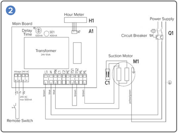 Legend:
- A1 – Control Circuit Board
- C1 – Capacitor
- H1 – Hour Meter
- M1 – Suction Motor
- Q1 – Protection Switch/Circuit Breaker — In = 12 A, Un = 240 V, Icu = 2 KA
- F1 – Fuse — In = 0.4 A, Un = 250 V (UL Required), Icu = 35 A
Follow-up time: The factory-made follow-up time of the suction system (dry vacuum system) is approx. 60 seconds. By turning the knob P2 on the timing relay, this running time can be adjusted.
Office main switch: If the starting signal from the dental chair is not available, a connection must be made between cable strand number 1 and number 3 of the control cable (picture 3.1 ). The NXT DryVac suction system (tankless dry vacuum system) starts when the office main switch and the protection switch on the control box are both switched on.
NOTE: 60 seconds is minimum follow-up time to purge vacuum lines prior to shutdown.
NXT DryVac

- A1 – Control Circuit Board
- F1 – Fuse — In = 0.4 A, Un = 250 V (UL Required), Icu = 35 A
- H1 – Hour Meter
- K1 – Motor Contactor
- Q1 – Protection Switch/Circuit Breaker — In = 12 A, Un = 240 V, Icu = 2 KA
- W1 – Main Power Supply
- W2 – Control Cable – Suction Motor
- W3 – Control Cable – Suction Contact
- R1 – Follow-up Time (factory set at 60 seconds)
Connecting the NXT DryVac to the NXT Hg5 Amalgam Separator
Connection of the sewerage tubes and pipes
 1.1 Air in
- 1.2 Amalgam Separator
- 1.3 NXT DryVac
- 1.4 Air out
- 1.5 Water out
Maintenance

Once daily, clean vacuum lines with PowerScrub Vacuum Line Cleaner. Ideally, cleaning with PowerScrub should be carried out before longer periods of downtimes of the dental unit.
It is recommended that the cuspidor should also be rinsed out daily with PowerScrub Vacuum Line Cleaner.
Cleaning of the Filters

The filters must be cleaned at least once a week. However, depending on the method of working, this may be necessary every day. A clogged prefilter is perceivable by a reduction of suction power.
- The filter at the suction tube holder, at the dental unit, cuspidor bowl (only if present)
- The vacuum filter (vacuum trap) on the suction machine
NOTE: Any residues from the prefilter, which might contain amalgam, must be disposed according to the local codes.
Exhaust air filter
The exhaust air bio-filter must be used if not discharged outdoors. Change once per year (only if present).
A yearly maintenance of the NXT DryVac is required
Yearly maintenance kit (item no: DRYVAC-NXT-MTK)
A yearly maintenance of the NXT DryVac is required: This includes the check valve of the air/liquid separation outlet, the filter grid and the inlays of the noise reducing item.
As always if you have any questions about this process or anything else please feel free to contact us and take advantage of our “FREE TECH SUPPORT.”
We also offer FREE VIRTUAL TECH SUPPORT to “See and Talk” with a “Real Time Live Technician” for any problems you may be in need of help with.
You can also use our “FREE MAINTENANCE PROGRAM”. Take the guesswork and worrying about what unit is due for maintenance and which maintenance cycle it is time for. We will keep track of all your autoclaves and let you know when it’s time for anything.
The NXY DryVac Tankless Dry Vacuum is available to purchase on our site here.