

VistaCool Model V7502 Installation Guide Leave a comment
This article is all about installation for the VistaCool V7502 System. And if you have any questions or just want to talk to someone, call our Free Tech Support at 704-966-1650 Option 3.
VistaCool V7502 Direct-to-Drain Thermal Reduction System for Autoclave Wastewater Installation Guide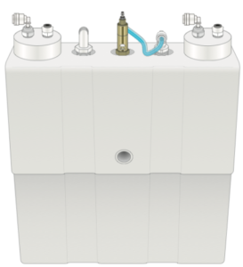
VistaCool systems eliminate the need for extra waste in your autoclave cleaning cycles by taking out the middle man. It removes the need for any extra condensation tanks by cooling the exhaust water and sends it directly down the drain. Today we’re going to show you how to install one of their popular and most effective models: the V7502. The VistaCool V7502 can handle up to 2 autoclaves connected to it at once, and with an adapter kit, becomes compatible with the following autoclaves:
- Midmark M3
- Midmark M9
- Midmark M11 (V7502 only)
- SciCan STATIM 2000
- SciCan STATIM 5000
For System Owners
Although actual installation of VistaCool is quite simple, it is recommended that a professional technician or plumber familiar with dental/medical offices should perform the installation since interface with a cold water line and drain is involved. He/she should be familiar with the local plumbing codes and techniques for successful dental/medical equipment installations.
Please keep the Installation Guide & Owner’s Manual handy for future reference and ensure that anyone responsible for operation and maintenance of the system is familiar with all details contained in this manual.
For System Installers
Please read this entire manual before proceeding with installation and operation, and always follow local plumbing codes.
VistaCool systems should only be installed on compatible autoclaves (listed above). Please check with the manufacturer of other brands of autoclaves or contact Vista Research Group before connecting to other than SciCan or Midmark autoclaves.
 PRECAUTIONS:
-
VistaCool systems can be installed on Midmark M9 & M11 units. Only M9, M9D, M11 and M11D units with green displays can be connected to VistaCool. First generation models with red displays units with green displays can be connected to VistaCool. First generation models with red displays
-
The VistaCool tank must be installed so that the top of the water tank is ABOVE the connection to the drain adapter.
- Check for leaks and run the autoclave(s) for at least two consecutive cycles after installation to ensure the system is operating properly.
Important Midmark Compatibility Information
- VistaCool systems can be installed on Midmark M9 & M11 units, but an adapter kit (S7560) is required. Only M9, M9D, M11 and M11D (-02X, -03X) units with green displays can be connected to VistaCool. First generation models with red displays (-0XX) cannot be connected to VistaCool.
- While approved for use with the Midmark M9 units, the single-unit VistaCool (V7501) should not be used with Midmark M11 units. The double-unit VistaCool (V7502) is capable of handling one or two M11 units (or any two compatible autoclaves).
Complete installation instructions for the M9 & M11 units are included with the S7560 adapter kit.
Preparation
Remove all contents from the VistaCool product carton to make certain all items needed for installation are present and undamaged.
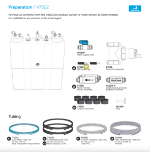
NOTE: A fitting (tee, compression fitting, etc) for connecting to cold water supply line is not included in this VistaCool kit and must be supplied by the installer/plumber See Plumbing section for more details.
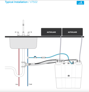
Typical Installation
Plumbing
NOTE: Be cautious in this step and pay careful attention to the images, as any mentions of numbers or letters in the text correlate to their respective duplicate in the images.
Whether installing a single or double-autoclave VistaCool unit, the cold water (coolant) supply and drain (condensate and coolant overflow) connections are exactly the same.
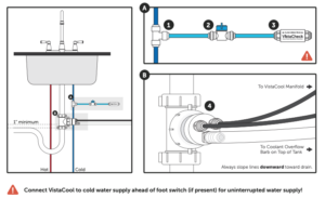
1.) Turn off water supply Tap the cold water line with a tee, valve, compression valve, etc (not included) The connection must be made by the installer so the 1/4” OD polyurethane tubing can be connected.
2.) Cut a 3” to 4” piece of the blue poly tubing and connect the installed fitting (from step 1) to the inlet of the inline water valve provided Be certain the valve is in the closed position (blue lever 90-degrees to the valve body)
3.) Cut another 3” to 4” piece of blue poly tubing and connect one end to the outlet end of the inline valve, and the other end to the inlet of the supplied CSA certified VistaCheck dual check backflow preventer.
4.) Measure the drain tee adapter assembly for placement into the drain piping Cut and remove a section (usually 1-1/2”) in the appropriate place above the trap as shown Keep the entire assembly as low as possible while maintaining a minimum of 1” off set from the barb fitting as shown Rotate the drain adapter hub so the barb fitting is at the 6:00 position.
Be sure to tighten slip-joint tee’s nuts once all steps are complete.
NOTE: When installing the black 1/4” OD condensate line with a V7501 system, make sure to install the white 1/4” plug in the remaining open fitting on the adapter to prevent water from flowing out of the drain. When installing a V7502 system, connect a black condensate line to each of the two 1/4” push-to-connect fittings and set the white plug aside.
(Part shown in right image.)
Cabinetry
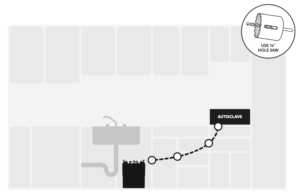
VistaCool systems are typically installed in the base/sink cabinet of sterilization centers. The systems should always be installed as close to the drain system and cold water supply line as possible. The 1/4” OD Teflon high temperature tubing will need to run from the output port of the autoclave directly to the VistaCool system. In many cases, holes will need to be drilled through one or more partitions in order to get the tubing from the autoclave to the VistaCool.
In order to protect the tubing from kinking or damage, grommets have been included with each system. Many cabinets are constructed of composite wood and some are metal It’s especially important to use the grommets to line the edges of the drilled holes in metal cabinets to keep the tubing from being damaged. Simply drill a 7/8” pilot hole through the metal or wood partition then push the smooth plastic grommet into the holes. Make sure to drill the holes so that the tubing makes a progressively descending angle from the autoclave to the VistaCool. The hole entering the cabinet where the VistaCool is installed should be above the top of the tank manifold so the tubing has a natural gravity angle to help prevent pools of liquid in the tubing.
NOTE: A 9’ coil of the high temperature Tefl on tubing is included with each single (V7501) and an 18’ coil is included with each double (V7502) VistaCool system. An additional 18’ coil of Tefl on tubing is available as an accessory (TU949). Do not exceed 10’ in length for any individual section of tubing between an autoclave and the VistaCool Always try to minimize the length of run of tubing to reduce friction and prevent “traps” and pooling in the lines.
Connecting the System
- All tubing cuts must be even and clean
- Most fittings are a push-to-connect design Use a twisting motion when pushing tubing into the fittings to ensure ends are fully inserted through the collet and into the internal “O” ring
- Several fittings are a hose barb design The 1/8” metal barbs are extremely strong and tight when the tubing is pushed on If you must remove the tubing for any reason, make a cut along the edge of the tubing at the barb then remove, make a fresh cut and reinstall
- The remaining barb connections are thermoplastic, and the tubing should be held in place sufficiently by being stretched over the barbs since there is no pressure in the lines However, if you feel the tubing could be pulled during normal use, you may wish to install a stainless hose clamp to hold the tubing firmly in place
- Do NOT use Vaseline or other lubricants (other than clean water) on the tubing Moisten the tubing ends with water before inserting tubing into push-to-connect fittings if lubrication is needed
- Cut the tubing to a sufficient length so that no tubing line is tight or stressed, and so the VistaCool tank assembly can be moved within the cabinet easily
- Tubing connecting to the drain (both the condensate lines and coolant line) should be as short as possible and must not droop, loop or sag in a way that would form a trap that could cause fl ow restriction or backpressure
- Ensure that fluid flow is not impeded by kinked or bent tubes
- Manually FILL THE TANK before starting the system. (See below)
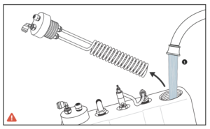
1.) Fill the water tank COMPLETELY. Remove the manifold and coil assembly from the tank by twisting the manifold counter clockwise. Fill the tank with COLD water, replace the coil manifold into the open hole and place the tank into position under the sink.
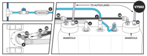
2.) Connect the cold water supply to the water tank using the blue, semi-transparent (1/4” OD x 1/8” ID) polyurethane tubing to the system. Continue the tubing from the outlet of the VistaCheck to the top stainless hose barb on top of the brass water valve on the thermal regulator. Optional: warm the end of the tubing with hot water before pushing it over the barb and make sure it is pushed down completely over the stem of the barb and is flush with the hex stainless base of the barb.
3.) Connect the high-temp Tefl on 1/4” OD tubing from the autoclave to the milky white Kynar fitting on top of the white manifold. Make sure the tubing does not kink when moving the autoclave or pulling the tubing through the cabinet partition holes.
4.) Connect the black 1/4” OD LLDPE condensate line tubing to the elbow fitting on the top of the manifold, then connect the other end to one of the male adapter fittings on the drain adapter.
5.) Cut the black condensate line (from step 4) as close to the drain adapter assembly as possible and install the in-line thermal sensor. Make certain the fl ow direction on the in-line sensor is oriented towards the drain.
6.) Connect one end of the 1/2” ID clear PVC tubing to the elbow hose barb on the tank and the other end to the straight 1/2” hose barb on the drain line adapter. Make sure the tubing is firmly engaged over the barbs If in doubt, use appropriate size hose clamps.
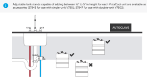
Tank Positioning
The VistaCool system should be installed so that the top of the water tank is above the coolant overflow fitting on the drain adapter assembly, and below the autoclave outlet. If the tank is below the level of the coolant overflow fitting, the system may not operate properly. Installing a tank at the wrong height may create resistance for proper water flow, since the system is designed to take advantage of gravity flow.
As always if you have any questions about this process or anything else please feel free to contact us and take advantage of our “FREE TECH SUPPORT.”
We also offer FREE VIRTUAL TECH SUPPORT to “See and Talk” with a “Real Time Live Technician” for any problems you may be in need of help with.
You can also use our “FREE MAINTENANCE PROGRAM”. Take the guesswork and worrying about what unit is due for maintenance and which maintenance cycle it is time for. We will keep track of all your autoclaves and let you know when it’s time for anything.
The VistaCool V7502 Double Autoclave System is available for purchase here.