
Flight A6 Radius Package Installation Guide
Proper installation, operation and maintenance are the most important things to know in terms of ownership of any device or instrument. Believe it or not, that even extends to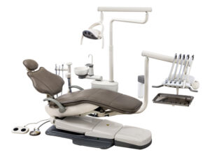 some of the biggest machines, like your dental operatory. Proper installation is vital to ensure that your machine starts its work without issue. Following proper operation will ensure that no complications arise during its use. And remembering proper maintenance can not only help your machines run smoothly… But it also helps to ensure longevity in your units. And when it comes to a dental operatory, a massive financial investment, you want to keep it in top shape.
But here at Sterilizer Autoclave Solutions, we make it our job to provide you with the proper knowledge to make sure everything goes smoothly for every phase of the process. We’ve written about the Flight Dental Systems A6 Radius Package. You can find the original article on our site here. But in this article, we’d like to focus on the proper instructions for installation with this dental operatory. We’ll be going over the installation instructions for the A6 Radius Package Operatory with instructions provided by the manufacturer. That way, you can ensure that your installation is up to snuff and prevent any issues down the line.
If you have any questions about the Flight Dental Systems A6 Radius Package, or anything else, please give us a call at 704-966-1650 Option 3 for our Free Tech Support line.
Tools Required for Installation
1. Allen (Hex) keys sets (Metric and Imperial)
4. Phillips screw driver – medium size
3. Slot head screw driver – medium size
4. Slot head screw driver – extra small size
5. Fish tape
6. Needle nose pliers – medium size
7. Moving dolly with pull rope
8. 10” Magnetic level
9. Standard pliers or cutters
10. Hammer drill
11. Utility knife
12. Handpiece pressure gauge
Basic Installation
This is a systematic overview with diagrams to help you quickly install the dental unit for operation. A two man team can install any Flight system in as little as one hour; however, it is preferred to have a minimum of three technicians in attendance for installation because of the weight of the equipment.
The Flight model operatory system is shipped fully assembled with the exception of upholstery and treatment light, which must be installed in the operating room. In most cases the chair can be unpacked by loading it on a shipping dolly and wheeling it into the operating room for final placement and connection to the plumbing and electrical fixtures.
In most cases, even with narrow doors or hallways, the system should fit through the door; the assistant arm and delivery system can be rotated out of the way and into the operating room.
Please note the overall dimensions of the chair and the delivery system relative to the dimensions of the door and the hallway prior to the transportation of the package into the operating room.
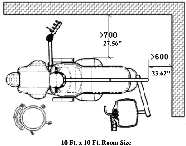
Positioning of Chair in Operating Room
Proper operation of the dental unit requires that sufficient space be left around the chair to accommodate the operator and assistant as well as entry and exit for the patient.
We suggest the unit should be arranged in the following manner according to the figure below.
Provision of Utilities to the Dental Unit
The FLIGHT system normally requires the provision of a compressed air line, vacuum line, a water supply, a 1½” or 2” drain and a 110/220V electrical supply. The necessary connectors will be found in a plastic bag stored within the floor box or inside the treatment tray. A backflow prevention device must be installed at the connection point of unit to office plumbing or elsewhere in the office in accordance with all federal, state, provincial, and local regulations.
Junction Box Utility Connections Specifications
AIR:
• ½” pipe N.P.T. protruding 1” from floor or wall. Supplied by contractor.
• Manual air shut-off valve to be installed by contractor.
• Air pressure 70-80 psi.
• Air plumbing should be flushed clean before making final connections to dental equipment.
WATER:
• ½” pipe N.P.T. protruding 1” from floor to wall. Supplied by contractor.
• Manual water shut-off valve to be installed by contractor.
• Water pressure 35-40 psi.
• Water plumbing should be flushed clean before making final connections to dental equipment.
ELECTRICAL:
• ½” conduit (or by code) and box with dual or equal receptacle supplied by contractor.
• Wire box as per code with top of the box no higher than 4½” above finished floor.
• Voltage: 115 Volts AC 3 wire or 230 Volts AC 3 wire.
CENTRAL VACUUM:
• Plumbing up to utility center should be specified by central vacuum supplier (usually 1¼”) and terminated in utility center with 1/2” OD connection perpendicular to floor, similar to drain connection.
GRAVITY DRAIN:
• ½”OD tube protruding 1” from finished floor. A 1½”pipe is recommended underground.
Note: Place trap in line and use vented fitting to conform to local codes. Supplied by contractor. Floor mounting only.
• Local regulations may require that licensed plumbers and electricians install utilities.
• Make sure all plumbing conforms to prevailing local codes.
Use the junction box template to determine floor locations for connections.
Installing the Floor (Junction) Box
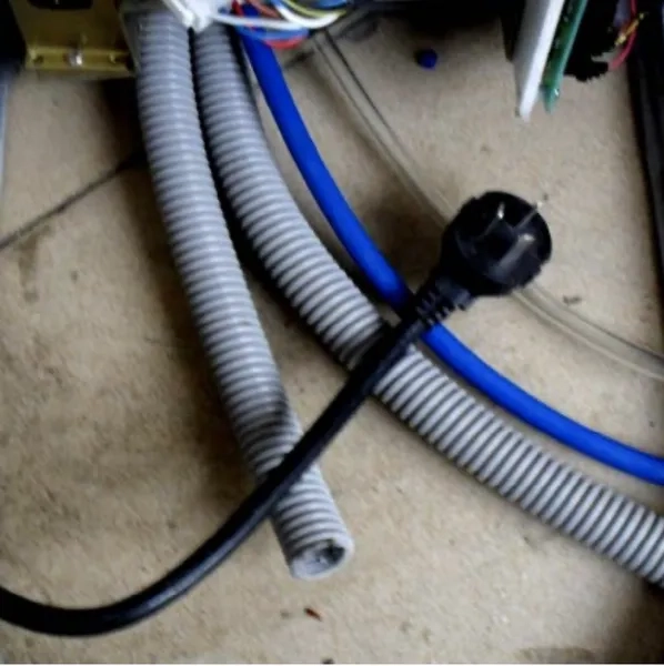
The floor box will be delivered connected by umbilical to the utility center. Be careful when moving the unit to avoid pinching the umbilical or any of the tubing within.
The floor box may be flush mounted or non-flush mounted depending upon the position of the utilities in relation to the desired chair position. If the floor box is to be flush mounted you can use a 2” drill bit to cut a hole in the rear of the floor box cover to allow the insertion of the chair power cord into the floor box.
The floor box may also be installed flush to the floor or resting on four rubber feet. If the floor box is installed using the rubber feet, the box will not be secured to the floor. If the floor box is to be mounted flush to the floor, you must remove the four rubber feet, and secure the floor box to the floor using four screws inserted through the holes previously occupied by the rubber feet.
Floor Box Installation
1. Prior to junction box installation it will be necessary to flush out the office plumbing.
2. Connect a hose to the water line and flush into a drain or suitable container. This will prevent debris getting into unit lines. Flush the air line also.
3. Locate the junction box template for general layout. If the box is to be secured to the floor, drill holes into floor and place the junction box frame over the office plumbing.
4. Secure frame to the floor.
5. Install the master shut-off valves. Using a 5/8” wrench, install the air and water shut-off blocks onto the master valves. Tighten the compression nuts securely.
If necessary, shorten drain and vacuum tubing as required.
Locate the air and water regulators in packaging. The incoming air and water pressures may be set using these regulators. The air pressure regulators are manufactured to handle air and water pressures that do not exceed 135 psi.
The Floor Box Dimensions and Plumbing
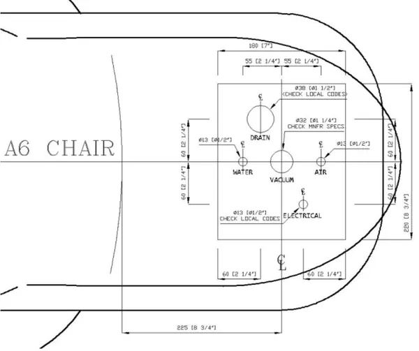
a) Water pipe, ½”.
b) Central vacuum pipe, 1¼” (or by specs).
c) Air pipe, ½”.
d) Drain pipe, 1½”, or by code.
e) Power conduit, as per code.
3/8” Compressed air connection
115v or 230v Electrical outlet
3/8” Water connection
19mm ID drain connection
16mm ID vacuum connection
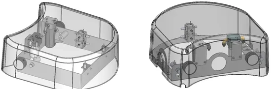
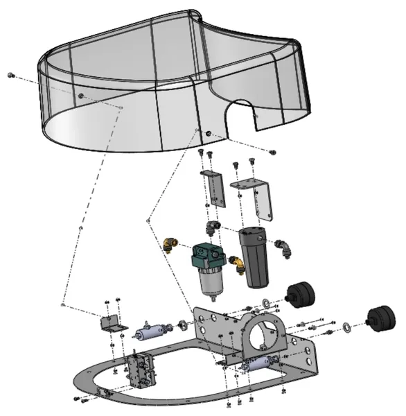
To remove the floor box cover, just grasp the end of the cover and lift it upwards. This does not require tools. On certain models in which pressure gauges are visible on the outside of the floor box cover, be careful that you do not disconnect or damage the tubings that are connected to the cover. Air and water pressure pre-regulators control the air and water pressure of the unit.
The air and water shutoff valves control the flow of air and water to the unit. These valves must remain fully open (turned clockwise) to prevent leaks. Only close the valves during servicing.
The air and water filter prevents solids from entering the unit.
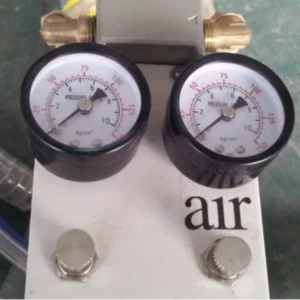 Adjust incoming Air and water bottle pressure in junction box.
The air pressure gauge will also regulate the incoming city water.
The air pressure should be 80psi and air pressure for your water bottle should be 35-40psi.
Floor box size is 7” x 8 5/8” or 180mm x 220mm.
All fittings for the connection of air/water/suction and drain are supplied with the unit.
Securing Chair Base
Flight provides a metal bracket to secure the chair base to the floor. This will help to provide additional stability for the chair and to prevent chance that the chair may cause any injury. A bracket is provided in your parts to secure the chair. Please see diagram of where to secure the chair to the floor.
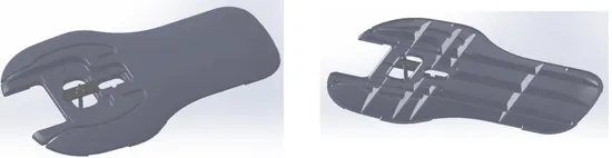
Please use the proper securing bolts according to your flooring material.
As always if you have any questions about this process or anything else please feel free to contact us and take advantage of our “FREE TECH SUPPORT.”
We also offer FREE VIRTUAL TECH SUPPORT to “See and Talk” with a “Real Time Live Technician” for any problems you may be in need of help with.
You can also use our “FREE MAINTENANCE PROGRAM”. Take the guesswork and worrying about what unit is due for maintenance and which maintenance cycle it is time for. We will keep track of all your autoclaves and let you know when it’s time for anything.