
Flight A6 Radius Package Operation Guide
Proper installation, operation and maintenance are the most important things to know in terms of ownership of any device or instrument. Believe it or not, that even extends to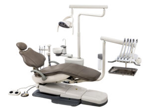 some of the biggest machines, like your dental operatory. Proper installation is vital to ensure that your machine starts its work without issue. Following proper operation will ensure that no complications arise during its use. And remembering proper maintenance can not only help your machines run smoothly… But it also helps to ensure longevity in your units. And when it comes to a dental operatory, a massive financial investment, you want to keep it in top shape.
But here at Sterilizer Autoclave Solutions, we make it our job to provide you with the proper knowledge to make sure everything goes smoothly for every phase of the process. We’ve written about the Flight Dental Systems A6 Radius Package. You can find the original article on our site here. But in this article, we’d like to focus on the proper instructions for operation with this dental operatory. We’ll be going over the operation instructions for the A6 Radius Package Operatory with instructions provided by the manufacturer. Your operatory will always be working at its most effective with proper operation being utilized.
If you have any questions about the Flight Dental Systems A6 Radius Package, or anything else, please give us a call at 704-966-1650 Option 3 for our Free Tech Support line.
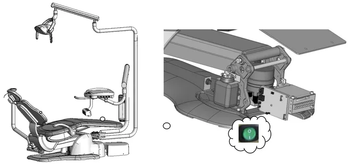
Power On/Off Button
The power on/off for the chair is a green switch located on right side of the chair base. The switch is illuminated when the chair is plugged in and the power is on. This allows the entire system to become functional at the touch of a button. When the power on/off button is pressed in, a buzzer will sound two times.When pushing a valid key, the buzzer sounds one time. When the power button is off, the system will not be functional.
Control Panels for Movement of the Flight Unit
Each Flight chair can be operated either manually or with programmed controls on the touchpads or on the deluxe foot control. Using the foot control or the arrows on the touchpad, the chair position can be manually controlled. Programmable functions can be stored in the designated memory buttons.
Touchpad Functions – On TRAD -2001 Treatment Tray
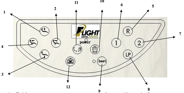
1. Chair base up
2. Backrest forward
3. Chair base down
4. Backrest down
5. Reset chair to original position
6. Memory position number 1
7. Memory position number 2
8. Return to last position
9. Syringe heater On/Off *
10. Activate cup fill (not used)
11. Activate bowl rinse (not used)
12. On/Off/Intensity – treatment light
*Syringe heater function is not available on chairs sold in Canada, United States or European Union.
Touchpad Functions – On Trad-2002/3001 Treatment Trays & Assistant’s Arm
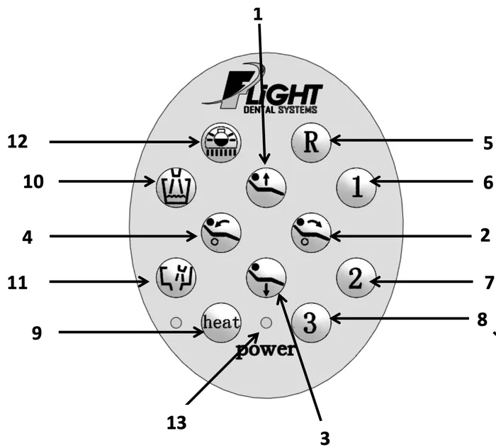
1. Chair base up
2. Backrest forward
3. Chair base down
4. Backrest down
5. Reset chair to original position
6. Memory position number 1
7. Memory position number 2
8. Return to last position
9. Syringe heater On/Off *
10. Activate cup fill (not used)
11. Activate bowl rinse (not used)
12. On/Off/Intensity – treatment light
13. Power indicator
*Syringe heater function is not available on chairs sold in Canada, United States or European Union.
Movement of chair
Manual Mode
The up and down keys allows for vertical movement of the chair. Press the up key to raise the chair and hold until desired height is reached or until the maximum height is reached. Press the down key to lower the chair and hold until the desired height or the maximum depression is reached.
The forward and backward keys allow for tilt movement of the chair. Press the forward key to tilt the chair forwards and hold until the desired position or the maximum forward tilt position is reached. Press the backward key to tilt the chair backwards and hold until the desired position or the maximum backward tilt position is reached.
Automatic Mode
This refers to programmable positions based on the practitioner’s desire and can be constantly changed according to preference and needs. There are two adjustable memory position keys (1 and 2). Pressing each key will activate the chair to move to the programmed position.
Pressing the reset key (R) will reset the chair to the original patient entry position. This position is preset at the factory.
Pressing the last position key position (LP key) will bring the chair backrest to the preset upright position allowing the patient to easily access a rinse cup. The chair may then be returned to the working position using the programmed position buttons.
The chair movement may be stopped at any time during automatic movement by pressing the directional keys on the touchpad.
Programming the Chair
The dental chairs have programmable positions that accommodate the doctor’s preferences. To Program your chair please follow these steps:
1. Adjust the chair to the desired position using the manual keys.
2. Once in place, press one of the memory position keys and hold for 5 seconds.
3. Wait for the buzzer to ring twice. Your position is now set.
To set the second memory position, move the chair to the second desired position and repeat step 2 using the other memory position button.
Setting the Chair Soft Limits
The maximum high and low setting for the chair may be field set according to the individual requirements of the office. It is recommended that these settings be set by the technician at the time of installation at not less than 1” from the mechanical high and low limits of the chair.
Resetting the Chair Soft Limits
Press the Reset and Chair Base Down key simultaneously for 20 seconds until the buzzer sounds continuously at a rapid rate. Release the two buttons as soon as the buzzer starts to beep continuously.
First set the “double high” position by moving the chair base to the highest positions and then down slightly so that it is away from the mechanical limit switch. Move the chair back all the way up and thendown slightly so it is away from the mechanical limit switch.
Press the LP key once and the “double high” soft limits will be memorized and the frequency of the buzzer will decrease.
Set the “double low” position by moving the chair base all the way down and then slightly up so it is away from the mechanical limit switch. Move the backrest all the way down and then slightly up so that it is away from the mechanical limit switch.
Press the LP key one more time, the sound of the buzzer will stop and the setting is finished.
Note: If the sound of the buzzer does not stop and continues to sound at a rapid rate in step 5, this means there is an error in the setting. Steps 2 to 5 will need to be repeated.
Upon completion of this procedure the chair base and backrests will not be able to move higher or lower than these preset limits. It is important that the higher position is adjusted before the lower position. The process cannot be reversed and must be programmed in this order; otherwise, other operations cannot be carried out.
The Headrest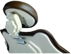
The FLIGHT chair includes a double articulating headrest. This headrest allows the placement of the headrest to virtually any position to ensure operator and patient comfort.
To set the position of the headrest, turn the knob at the back of the headrest in a counterclockwise direction to loosen the headrest movement.
Position the headrest in the desired position and tighten the knob by turning in a clockwise direction to fix the headrest in the desired position.
The height of the headrest is adjusted by pulling and/or pushing the headrest from the slot in the backrest.
When the glide bar reaches its maximum recommended working height (lower or upper), a marker will become visible on the headrest support. Do not use the headrest if the warning is visible.
Wheelchair Patients
The headrest can also accommodate patients in wheelchairs.
To adjust for wheelchair patients:
Slide the glide bar of the headrest upwards until it is away from the dental chair.
Rotate the glide bar 180 º and slide it back into the backrest pushing it completely down.
Position the dental chair into its fullback up position.
The patient should be positioned so the wheelchair is back to back with the dental chair. You may need to position the chair height to accommodate the patient’s height.
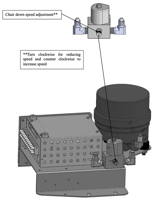
Patient Chair Up/Down Speed Adjustment
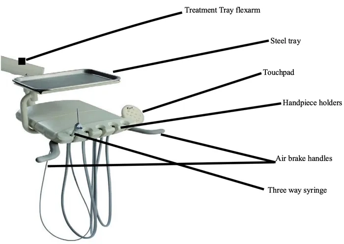
About the Delivery System
The Flight doctor’s delivery system includes a treatment tray with automatic control of three installed handpiece positions; two of these positions are configured for high-speed air turbine sets and one is configured for a low-speed air driven handpiece. The control also includes one air-water syringe set. The handpieces become automatically active when removed from the hanger.
It has a pivoting handpiece bar and rotating handpiece holders for personalized positioning. It holds up to 5 handpiece positions. The assistant’s instrumentation has an extended flexible arm for comfortable positioning and movement in the case of a solo operator.
Power On/Off Switch
The power on/off switch is located on the chair base. It is a green switch that lights when the unit is on.
When this switch is on, electrical power is running through the unit. The power switch should be turned off when the unit is not in use for extended periods of time – i.e. at the end of every day and at long breaks during the day.
Master On/Off Switch
This switch turns on/off the delivery system providing air and water for the entire unit. It will allow the user to operate the handpieces and treatment light when this switch is in the on position. The Master switch should be turned off when the unit is not in use for extended periods of time – i.e. at the end of every day and at long breaks during the day.
Anti-Retraction
The unit is equipped with certain anti-retraction devices; however, only instruments with anti-retraction devices are to be used with this dental unit.
Model: TRAD – 2002
Internal View of Doctor’s Handpiece Control System
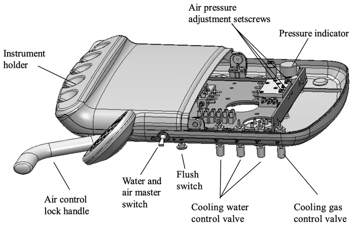
Operation of the Handpiece System
Each handpiece will become active when it is removed from the handpiece hanger. If a second handpiece is removed from the hanger, only the first handpiece will operate. This is a safety feature that cannot be changed. Be sure to check the recommended air pressures for your handpieces and have the individual pressures set according to these requirements by your technician.
Assistant’s Instrumentation
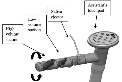
The assistant’s instruments will be installed at the factory including an air-water syringe, high volume evacuator and saliva ejector. The assistant’s hanger bar will include a fourth position that will be empty at the time of delivery.
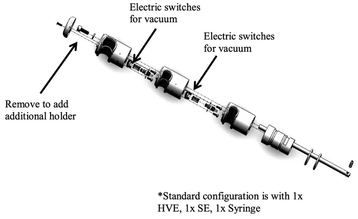 *Standard configuration is with 1x HVE, 1x SE, 1x Syringe
Should you wish to add a second high volume evacuator (HVE) valve, you may order the valve and tubing from your Flight representative although any standard HVE tubing and valve will fit. To install the additional HVE valve insert the tubing through the empty hole in the bottom of the utility center beside the entry holes for the existing vacuum tubings. Connect this end of the new HVE tubing to the vacuumtrap located within the utility center. Be sure to remove the seal within the extra vacuum line on the vacuum trap prior to installing the new vacuum tubing.
Note: Use HVE lines with an appropriate adapter to prevent biomatter from going back into patients oral Cavity.
Operation of Assistant’s Instrumentation
 The assistant’s instrumentation consists of a saliva ejector, syringe and high volume evacuator. It is configured with a distilled water bottle system and a port for water output.
Self-Contained Water System
The self contained water bottle system supplies water to handpieces and syringes. A 750ml bottle is provided for the user, you may install a 1.5 L bottle on there as well.
Adding Water to Water Bottle
Turn off the switch for air pressure of the waterbottle, thenunscrew the bottleto add the water. After adding the water, screw the bottle back to its original place and turn on the switch for the air pressure of the water bottle.
Note: Before unscrewing the bottle, you have to turn off the switch for the air in the bottle to avoid danger of causing harm/injury to yourself or from damaging the water bottle.
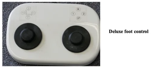
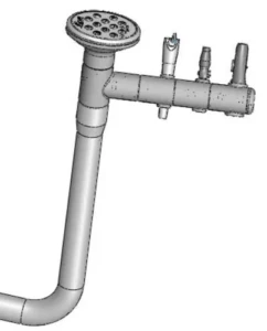
Operation of Handpiece Foot Control
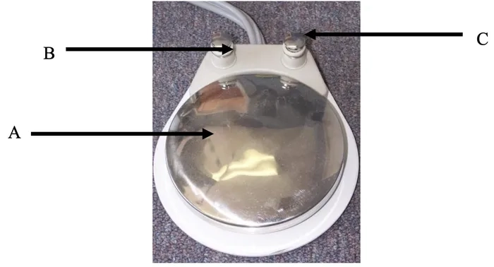
A- Activates the drive air for handpieces
B- Handpiece water on-off switch (wet/dry toggle)
C- Chip air blower – allows operator to blow air from the handpiece without operating the turbine or generating coolant water spray.
Floor Box
The floor box is an essential component of the dental unit. It regulates the delivery system and assistant’s instrumentation. It is mounted over the utilities on the floor of the room. The floor box houses the air and water manual shutoff valves, pressure pre-regulators, filters, vacuum and gravity drains, and electrical outlets.
As always if you have any questions about this process or anything else please feel free to contact us and take advantage of our “FREE TECH SUPPORT.”
We also offer FREE VIRTUAL TECH SUPPORT to “See and Talk” with a “Real Time Live Technician” for any problems you may be in need of help with.
You can also use our “FREE MAINTENANCE PROGRAM”. Take the guesswork and worrying about what unit is due for maintenance and which maintenance cycle it is time for. We will keep track of all your autoclaves and let you know when it’s time for anything.