
Flight A12 Operatory Operation Guide
Proper installation, operation and maintenance are the most important things to know in terms of ownership of any device or instrument. Believe it or not, that even extends to some of the biggest machines, like your dental operatory. Proper installation is vital to ensure that your machine starts its work without issue. Following proper operation will ensure that no complications arise during its use. And remembering proper maintenance can not only help your machines run smoothly… But it also helps to ensure longevity in your units. And when it comes to a dental operatory, a massive financial investment, you want to keep it in top shape.
But here at Sterilizer Autoclave Solutions, we make it our job to provide you with the proper knowledge to make sure everything goes smoothly for every phase of the process. We’ve written about the Flight Dental Systems A12 Operatory. You can find the original article on our site here. In this article though, we’re covering the operation guide, with instructions provided by the manufacturer. Operation is key to ensuring that every process goes smoothly from start to finish. And it can save from potential hiccups down the line with your unit.
If you have any questions about the Flight Dental A12 Operatory, or anything else, please give us a call at 704-966-1650 Option 3 for our Free Tech Support line.
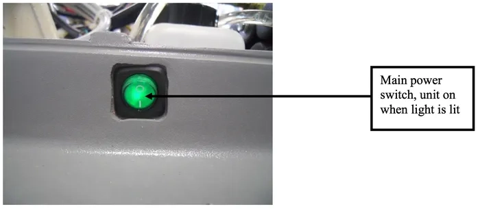
Power On/Off Button
The power on/off for the chair is a green switch located on right side of the chair base cover. The switch is illuminated when the chair is plugged in and the power is on. This allows the entire system to become functional at the touch of a button. When the power on/off button is pressed, a buzzer will sound two times, while pushing the valid key, the buzzer sounds one time.
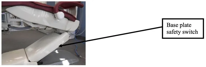
Chair Safety Stop Plate
The chair is equipped with an automatic stop plate located on the underside of the chair lift arm.
The stop plate stops the chair movement immediately if the chair is lowered onto a fixed item.
The chair will not move until the plate is released from its activated position.
Touchpad Functions (Figure 1)
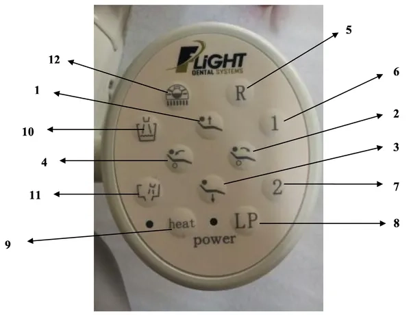
1. Chair base up
2. Backrest forward
3. Chair base down
4. Backrest down
5. Reset chair to original position
6. Memory position number 1
7. Memory position number 2
8. Return to last position
9. Syringe heater On/Off *
10. Activate cup fill
11. Activate bowl rinse
12. On/Off/Intensity – treatment light
*Syringe heater function is not available on chairs sold in Canada, United States or European Union.
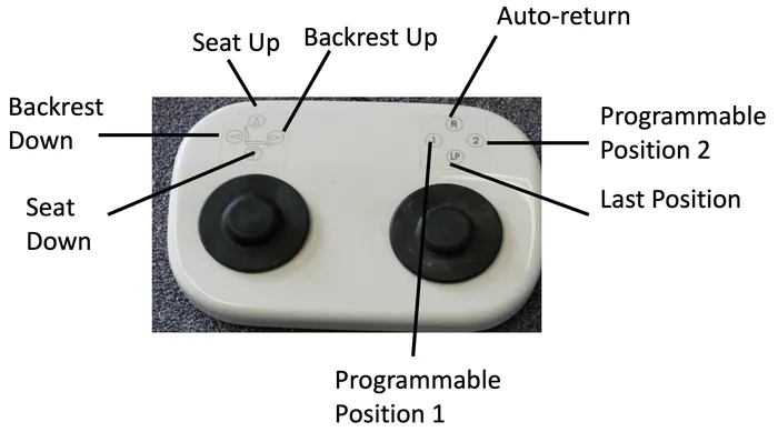
Deluxe Foot Control
Movement of chair
Movement via Touchpad or Foot Control
The up and down keys allow for vertical movement of the chair. Press the up key to raise the chair and hold until the desired height is reached or until the maximum height is reached. Press the down key to lower the chair and hold until the desired height or the maximum height is reached.
The forward and backward keys allow for the backrest movement of the chair. Press the forward key to tilt the chair backrest forward and hold until the desired position or the maximum forward tilt position is reached. Press the backward key to tilt the chair backwards and hold until the desired position or the maximum backward tilt position is reached.
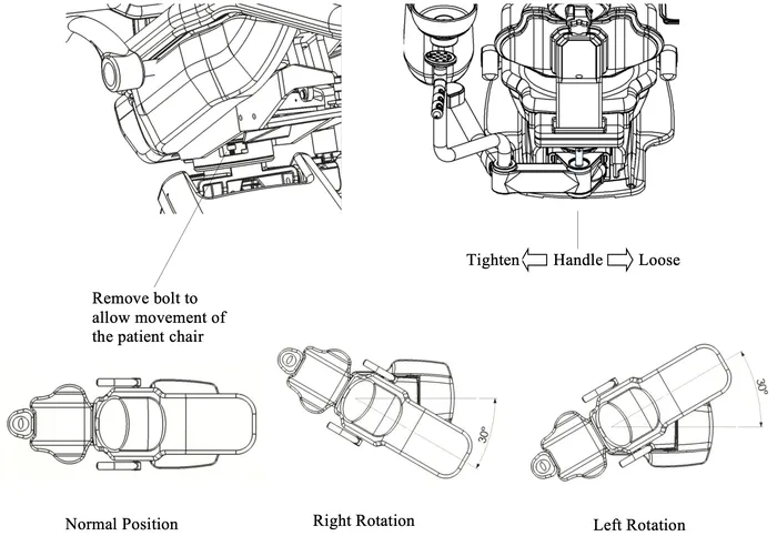
Rotation of Chair
Unlock the fixed latch at the bottom of the machine.
Loosen the handle.
You can now rotate the chair left and right by 30 degrees.
See below:
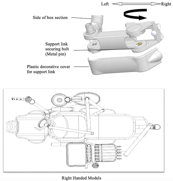
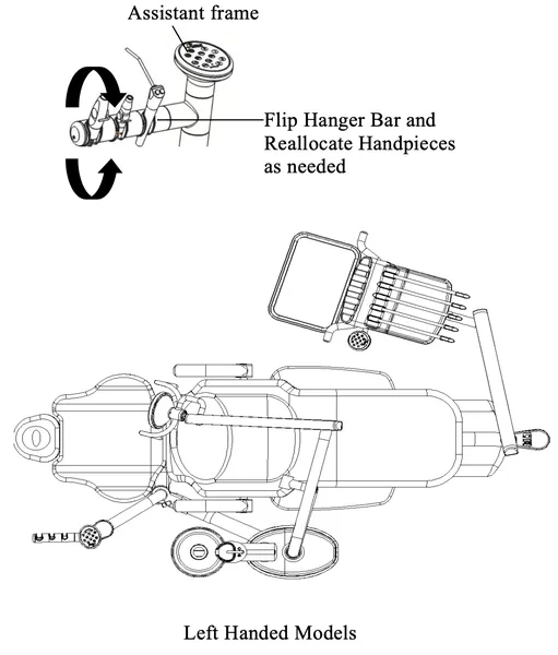
3.3. The A12 Operatory is installed by default for right-handed operation. If you need to convert the unit for left-handed operation, follow the instructions below.
3.3.1. First, remove the plastic decorative cover for radius mounting arm bracket.
3.3.2. Remove metal pin from the bracket to allow the bracket to move freely.
3.3.3. Rotate the whole bracket, cuspidor, and assistant arm assembly to the right side of the chair and replace metal pin to its original position. Replace the plastic cover over the radius mounting arm bracket.
3.3.4. Turn the assistant instrumentation to the appropriate position.
Automatic Mode
This refers to programmable positions based on the practitioner’s desire and can be constantly changed according to preference and needs. There are two adjustable memory position keys as illustrated in figure 1. Pressing each key will activate the chair to move to the programmed position (labeled 1 and 2).
Pressing the reset key (R) will reset the chair to the original patient entry position. This position is preset according to chair soft limits.
Pressing the last position key (labeled LP or 3) will bring the chair backrest all the way into the upright position for Cuspidor or X-ray use.
The chair movement may be stopped at any time during automatic movement by pressing any of the directional keys on the touchpad.
Programming the Chair
The dental chairs have programmable positions that accommodate the doctor’s preferences. To program your chair please follow these steps;
1. Adjust the chair to the desired position using the manual keys.
2. Once in place, press one of the memory position keys (1 or 2) and hold for 5 seconds.
3. Wait for the buzzer to ring twice. Your position is now set.
4. To set the second memory position, move the chair to the second desired position and repeat step 2 using the other memory position button.
Setting the Chair Soft Limits
The maximum high and low setting for the chair may be field set according to the individual requirements of the office. It is recommended that these settings be set by the technician at the time of installation at not less than 1” from the mechanical high and low limits of the chair.
Setting up the Chair Limits
1. Press the Reset (R) and Chair Base Down key ↓ simultaneously until the buzzer. sounds at a fast rate. This indicates that the chair is in its software limits setting program.
Release the two buttons when the buzzer starts to beep.
Setting the “Double High Position”
2. Press up ↑ & hold till the chair has reached the highest position
3. Press right → & hold till the backrest is to its maximum forward position
4. Press LP to set the limit. You will start hearing a slower beep rate.
Setting the “Double Low Position”
5. Press down ↓ & hold till the chair has reached the lowest position
6. Press left ← & hold till the backrest is to its max backward position
7. Press the LP key one more time, the sound of the buzzer will stop and the setting is finished.
Upon completion of this procedure the chair base and backrests will not be able to move higher or lower than these preset limits. It is important that the higher position is adjusted before the lower position. The process cannot be reversed and must be programmed in this order otherwise other operations cannot be carried out.
The Headrest
All Flight Dental System’s chairs includes a double articulating headrest. This headrest allows the placement of the headrest to virtually any position to ensure operator and patient comfort.
To set the position for the headrest, turn the knob at the back of the headrest in a counter- clockwise direction to loosen the headrest movement. Position the headrest in the desired position and tighten the knob by turning it in a clockwise direction to fix the headrest in the desired position.
The height of the headrest is adjusted by pulling and/or pushing the headrest from the slot in the backrest. When the glide bar reaches its maximum recommended working height (lower or upper), a marker will become visible on the headrest support. Do not use the headrest if the warning is visible.
Wheelchair Patients
The headrest can also accommodate patients in wheelchairs.
To adjust for wheelchair patients:
1. Slide the glide bar of the headrest upwards until it is away from the dental chair.
2. Rotate the glide bar 180 º and slide it back into the backrest, pushing it completely down.
3. Position the dental chair into its fullback up position.
4. The patient should be positioned so the wheelchair is back to back with the dental chair.
You may need to position the chair height to accommodate the patient’s height.
Armrest Positioning
The armrest on the A12 chair is adjustable allowing for the ease of entrance and exit for the patient as well as additional comfort.
About the Delivery Unit
Assembling Chair Delivery Unit
Adjusting the cuspidor box
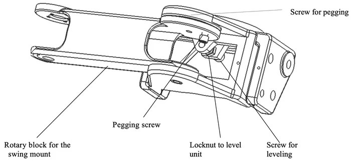
A. Adjust the pegging screw on the swing mount arm if it is not rotating smoothly.
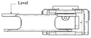
B. To adjust the leveling of the swing mount, loosen the locknut and then adjust the screw to level. You can make the block level and then tighten the screw when it is level.
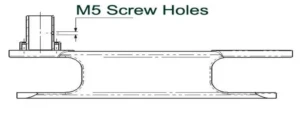
Schematic of Swing Mount and Assistant Arm Assembly
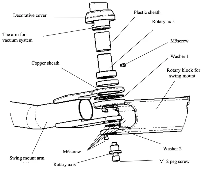
M5 screw should be installed as below:
 Leveling the Delivery Unit Arm
Schematic for Curved Post Attachment to the Chair
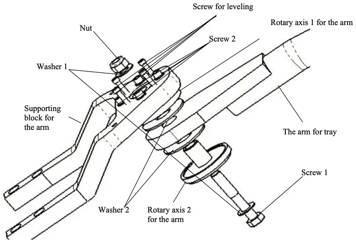
– Install the arm for the treatment head as shown above and adjust the level of the arm. Before adjusting the level of the arm, make sure that the base is level.
– To adjust the level of the delivery arm, loosen screws as shown in above diagram first (total 4 pcs), then adjust the screws for leveling to make the arm level as below:
Programming the Cuspidor Functions
Set the Volume for Cup Fill
The Flight unit allows for remote filling of the cup by either the doctor’s or the assistant’s touchpad. The volume of water can be preset to suit the needs of the office and depending on the standard cup size used in the office. Preset from either touchpad using the following steps:
1. Place a standard cup on the cuspidor beneath the cup fill spout.
2. Press the cup fill and cuspidor rinse buttons at the same time to enter the programming state
3. Press the cup fill button allowing water to run until the cup is filled to the desired level. Then release the button.
4. Press the LP button to save this volume setting.
Set the Bowl Rinse Function
The duration for rinse of the cuspidor may also be set to 15, 30, or 45 seconds or continuous flow using either the doctor’s or the assistant’s touchpad as follows:
1. Press the cup fill and cuspidor rinse buttons at the same time to enter the programming state
2. To set the cuspidor rinse for 15 seconds press the cuspidor rinse button once. The buzzer will ring one time. Press the LP button to save this time setting.
3. To set the cuspidor rinse for 30 seconds press the cuspidor rinse button twice. The buzzer will ring two times. Press the LP button to save this time setting.
4. To set the cuspidor rinse for 45 seconds press the cuspidor rinse button three times. The buzzer will ring three times. Press the LP button to save this time setting.
5. To set the cuspidor rinse for continuous flow press the cuspidor rinse button four times. Press the LP button to save this time setting. If this setting is implemented, the cuspidor will have to be turned off using the touchpad.
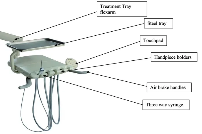
Operating Instruction for Treatment Tray
Model: TRAD-2001

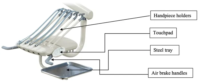
Model: TRAD – 2002
Model: CONT-3002
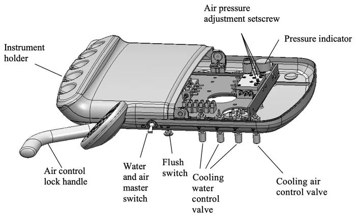
Internal View of Doctor’s Handpiece Control System
Function
Air Control Lock Handle
- This switch is always on. It is used for locking the flexible arm. When you want to adjust the height of the arm, depress this button and you will be able to move the arm. Release the brake switch when finished and the arm will not move and will remain at your desired position.
Pressure Indicator
- The gauge will show that the air pressure for hand piece is working if it is moving.
Water and Air Master Switch
- This switch controls the master on/off for the air and the water of the unit. When it is off, no water and air is supplied to the unit. When you are finished working, please turn off the switch in order to protect the unit.
Flush Switch
- This switch is for all 3 hand pieces on the unit. If you take one handpiece and push this switch, then this handpiece will be flushed.
Cooling Water Control Valve
- The adjustment needle valve controls each handpiece independently. Turn it clockwise to decrease water flow, and turn it counter-clockwise to increase water flow.
Cooling Air Control Valve
- One adjustment valve controls the cooling air for all three handpieces. Turn it clockwise to decrease air flow and turn it counter-clockwise to increase air flow.
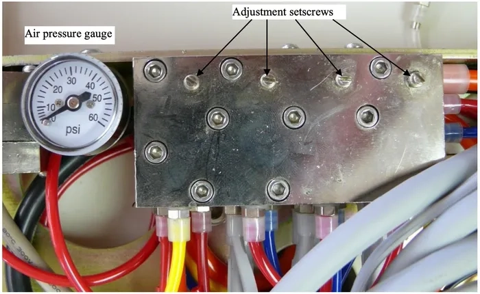
Air Pressure Adjustment Knob
- Each valve controls the air pressure for one handpiece. Turn it clockwise to decrease air pressure and turn it counter-clockwise to increase the air pressure. If the air pressure of the compressor is stable, it does not need to be adjusted constantly. (Refer to your individual handpiece manual for air pressure settings that are recommended from original manufacturer.)
Instrument Holder
- From left to right the holders are for the three-way syringe, handpiece 1, handpiece 2, handpiece 3, and lastly for the built-in scaler.
Note: The three-way syringe and each handpiece needs to be put in the right position or water may leak from other hoses when operating
Adjustments
1. Turn on water and air to the chair and check if the unit has any leaks.
2. Adjust the air pressure of the water bottle system to 2.8 kg/cm²or 40 psi.
3. Adjust the air pressure of the high speed hand piece to 2.5 kg/cm² (32-35 psi) and the lowspeed handpiece to2.1kg/cm² (30 psi)
The Operation of HandPiece Foot Control
A. Foot control for hand piece
B. Water on/off switch
C. Switch for chip air
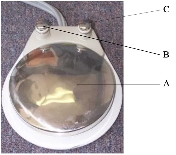
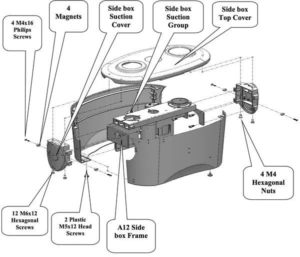
Diagram of Utility Box
Adding Water to Water Bottle
As in the photo above, open the cover first, turn off the switch for air pressure of the water bottle, then unscrew the bottle to add the water. After adding the water, screw the bottle back to its original place and turn on the switch for the air pressure of the water bottle.
Note: Before unscrewing the bottle, you have to turn off the switch for the air in the bottle to avoid danger of causing harm/injury to yourself or from damaging the water bottle.
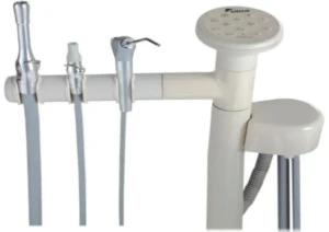
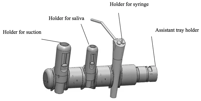
Assistant Instrumentation
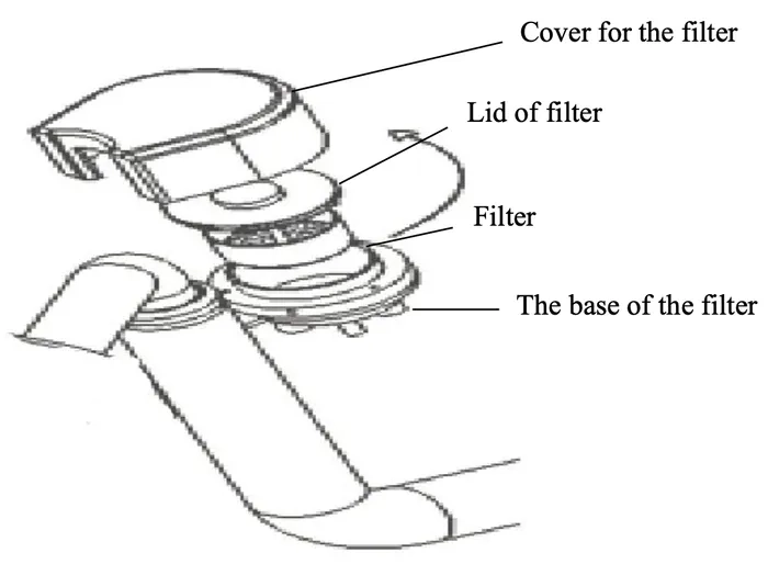
Clean the filter:
1) As the photo below: Remove the cover for the filter.
2) Unscrew the lid of the filter by turning it counter-clockwise.
3) Remove the filter and then clean out the dirt in the filter.
The holders for suction, saliva, and syringe can be seen below (respectively):
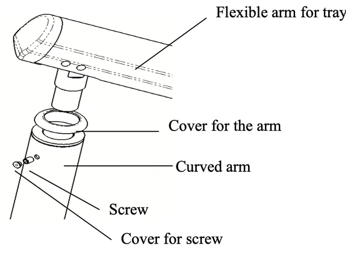
Light Arm Adjustments
Procedure to Adjust the Light Arm
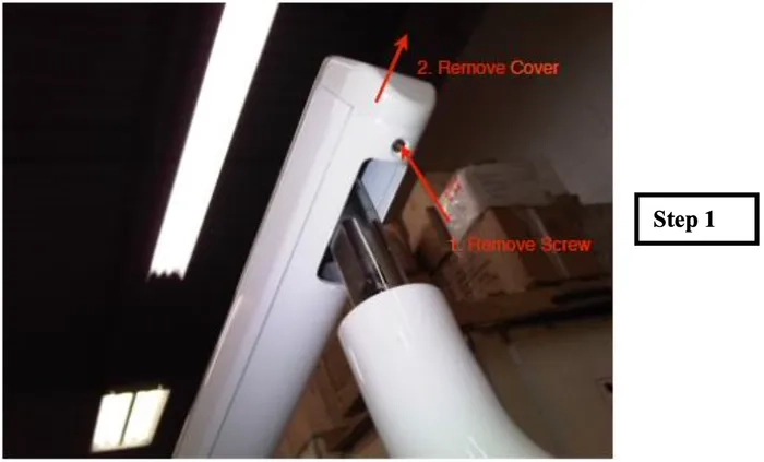
1. Remove screw securing plastic cover, and then slide the plastic cover off.
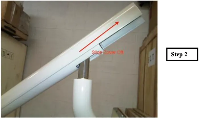
2. Slide the metal casing in the direction shown above to get access to adjustment knob inside.
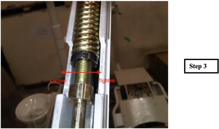
3. Shown above, the adjustment knob and tension screw.
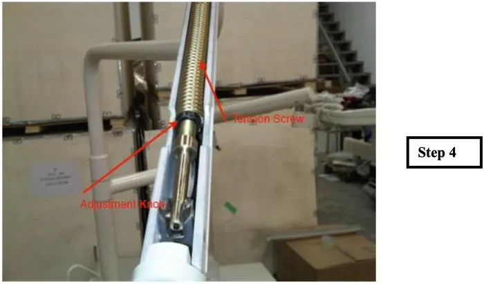
4. Adjust the adjustment knob clockwise to increase tension until desired level. Adjust counter-clockwise to loosen knob and decrease weight supported by the arm
Adjusting the speed of the Dental Chair
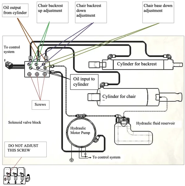
– You may adjust the speed of the chair by adjusting the flow of oil into and out of the cylinder.
– Note, when adjusting the speed of the backrest, the flow of input oil and output oil should be equal
– The speed was adjusted before the chair leaves the factory, it should not require any adjustment by the user, if adjustments are necessary, please ask an authorized Flight Dental Systems Service Technician to adjust it.
Note: Do not adjust the 3 screws on the bottom of the picture.
Adjusting the Chair Potentiometer
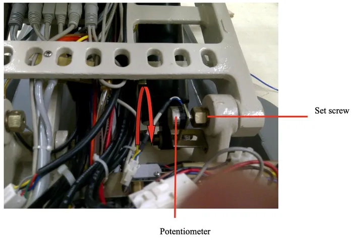
Adjusting Chair Base Potentiometer
1. Remove potentiometer from its assembly by loosening the set screw as shown above
2. Once the potentiometer is removed from its original position raise the chair base to the highest point
3. Turn the potentiometer counter-clockwise to its maximum position as per red arrow shown above, and then turn it clockwise slightly so that it is slightly away from its mechanical maximum
4. Install the adjusted potentiometer to its original position and tighten the set screw to secure the potentiometer. Do not move the chair position until the potentiometer has been reinstalled.
Adjusting Backrest Potentiometer
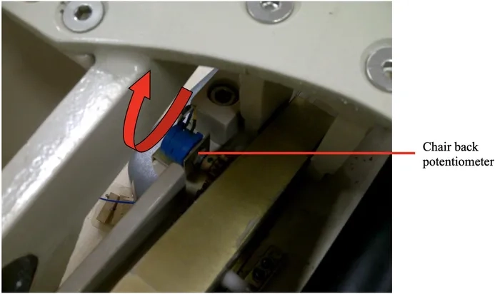
1. Remove potentiometer from its assembly by unscrewing the nut holding it to the metal bracket
2. Once the potentiometer is removed from its position raise the chair back to the upright position
3. Wind the potentiometer clockwise to its maximum position as per red arrow shown above, and then turn it counter clockwise slightly so that it is just slightly away from its maximum.
4. Install the adjusted potentiometer to its original position and tighten the screw without moving the chair
Fine Adjustments When Treatment Tray is Drifting
If the tray moves by itself, then tighten the hex screw shown above slightly to add friction to the arm
Leveling of the Treatment Tray Unit Head
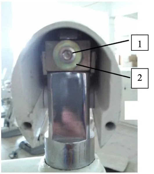
To balance the treatment tray unit head loosen the smaller hex screw (1 in above illustration) first and then you can proceed to adjust the second screw (2) to adjust the leveling of the tray. Once you are satisfied with the level of the tray you can tighten the hex screw (1) to secure its position.
Major Adjustments for Treatment Tray Arm
What you will need in order to adjust a A12 delivery unit arm are the following items — please cross reference them with the picture shown in (Exhibit A): Item A: 11/16 wrench, Item B: 8mm Allen Key (preferably a socket wrench attachment), Item C: 6mm Allen Key (preferably a socket wrench attachment), Item D: Socket wrench extension, Item E: Socket wrench.
Note: It is advised that this adjustment is done by two people – one person to hold the delivery unit arm and another person to make the adjustments as necessary. Also, the delivery unit arm itself is relatively heavy; consequently, if the delivery unit arm were to completely disconnect from the bracket, having two people in attendance will make it less likely that an injury will occur.
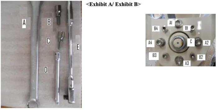
Exhibit B Explanation: In Exhibit B, you will notice three letters; each letter has a purpose in the assembly of the delivery unit arm. Its functionality will be explained below:
Letter A: These are the 4 large securing Allen screws labeled as A1 through A4. They help distribute the weight of the delivery unit arm equally.
Letter B: These are the 4 adjusting Allen screws labeled as B1 through B4. They are essential in the balancing of the delivery unit arm.
Letter C: This is the main center bolt connecting the delivery unit arm assembly to the bracket.
Please ensure that this is tightened to the utmost, and also ensure that when adjusting this, you do not loosen it fully, unless of course you are removing the delivery unit.
Step 1: Adjusting the A-type securing Allen Screws.
Take your socket wrench with an 8mm attachment or a regular 8mm Allen key and loosen the 4 A-type Allen screws.
Step 2: Adjusting the B-type balancing Allen Screws.
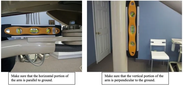
Take your 6mm Allen key and with a level placed on the horizontal portion of the arm, slowly adjust the B-type screws one screw at a time until level.
Now attach the level to the vertical portion of the arm. If the vertical level is not in balance, slowly adjust the B-type screws one screw at a time until level.
Now, place the level on the horizontal portion of the arm to make sure that it is still leveled. If not, repeat the process until the level is centered on both the horizontal and vertical portions of the arm.
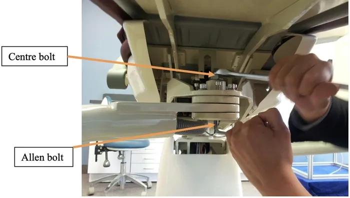
Step 3: Adjusting the main bolt connection to the bearing system, and sway arm assembly.
For this step you will need the 11/16 wrench. Place the wrench on the centre bolt and adjust it in a clockwise pattern until it is completely tightened. This is very important because this is the part that connects the delivery unit arm to the bearings and consequently to the remainder of the chair.
Note: The centre bolt is bolted onto an Allen bolt. When tightening the centre bolt make sure to simultaneously hold the Allen bolt in position – i.e. turn the Allen bolt counter-clockwise (viewed from the top) while simultaneously turning the centre bolt clockwise, as pictured below:
Adjusting Handpiece Hanger Valves
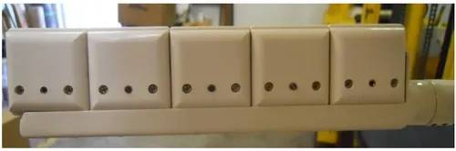
If handpieces are leaking water when activating the air foot pedal you may need to adjust the hanger valve for the individual hanger that is experiencing the problem.
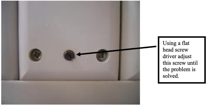
*Note that all hanger valves are preset at the factory and do not require any adjustment unless there is a problem. Please have an authorized Flight technician make any adjustments.
As always if you have any questions about this process or anything else please feel free to contact us and take advantage of our “FREE TECH SUPPORT.”
We also offer FREE VIRTUAL TECH SUPPORT to “See and Talk” with a “Real Time Live Technician” for any problems you may be in need of help with.
You can also use our “FREE MAINTENANCE PROGRAM”. Take the guesswork and worrying about what unit is due for maintenance and which maintenance cycle it is time for. We will keep track of all your autoclaves and let you know when it’s time for anything.